
Preparing the SZ-3.6 grain-fertilizer seeder for field work
12 min read
The industry produces a family of grain-fertilizer drills of various modifications. The basic model of the family of trailed row drills is the SZ-3.6 drill. It is intended for row sowing of seeds of cereals, grain legumes, grain crops, and certain other crops with simultaneous application of granular mineral fertilizers into the rows. Preparing the SZ-3.6 drill for operation includes checking its completeness and correct assembly, adjusting the openers, setting the sowing units to the specified application rate of seeds and fertilizers, as well as setting markers.
CHECKING COMPLETENESS AND CORRECT ASSEMBLY In the seed and fertilizer boxes, it is checked that there are no gaps or foreign objects. Sowing units must be checked particularly carefully: the ease of shaft rotation, the reliability of attaching the sowing unit housings to the box, the working length of the reels, and the degree of valve opening. The shafts of the grain-sowing units must move freely in the axial direction using the sowing regulator levers. When the reels are fully pushed into the housings, their ends should be flush with the plane of the sockets. Protrusions of individual reels are eliminated by shifting the sowing unit housings relative to the reels due to elongated holes for the bolts fastening the housings to the bottom of the box. Seed tubes are checked for plugs of germinated seeds or accidental objects. For disc openers, the freedom of disc rotation is checked, as well as the cutting edges, the thickness of which should be no more than 0.5 mm. Shaped cotter pins must be installed on the same hole of the opener rods. The exception is openers located opposite the tractor wheels. The pressure of their springs must be higher than the others. The air pressure in the chambers of the pneumatic support-drive wheels is 0.15–0.20 MPa. It is best to arrange the openers to the specified row spacing on an installation board. The center of the drill is marked on it, after having placed the board between its wheels and aligning the mark on it with the plumb line of the drill's center. After this, the opener linkage fasteners are loosened, and the openers are aligned with the marks on the installation board, applied at 30 cm intervals for the front and rear row openers. Setting units to the specified application rate of seeds and fertilizers. The drill is set to the sowing rate before moving to the field. First, the seed sowing rate q (kg) is calculated for a specific number of revolutions of the support-drive wheels (usually 15 revolutions are taken) using the formula: q =
15 10 ∙ 2 where 15 is the accepted number of wheel revolutions of the drill; Q is the set application rate, kg/ha; πD is the wheel rim length, m; B is the working width of the drill, m; a = 1.05 is a coefficient accounting for wheel slippage.
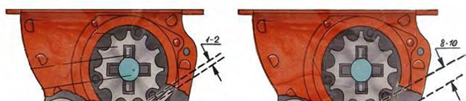
The values of Q, πD, and B are selected according to the instructor's guidance. The number 2 in the denominator of the formula shows that the calculation is carried out only for half of the drill's sowing units. Verification of the actual seed sowing is carried out as follows. According to the diagram, taking into account the specified rate, the length of the working part of the reel is determined. For example, the wheat seed sowing rate is 170 kg/ha. Efforts are made to ensure that the sowing rate is provided by the maximum extension of the working part of the reels and the lowest possible gear ratio in the transmission scheme. In this case, seeds are sown more evenly and are crushed less. In this example, the second option should be chosen. Taking into account the recommendations, the required gear ratio (in our example i = 0.428) is set in the gearbox using interchangeable gears. The gap between the valve and the lower edge of the sowing unit coupling is set to 1–2 mm when sowing seeds of cereal crops, and 8–10 mm when sowing grain legumes. Then the drill frame is jacked up so that one of the wheels can rotate freely. One half of the seed box is filled with seeds, and a tarp is spread under the openers or small bags are tied under the seed tubes. The drive wheel is rotated 2–3 times so that the sowing units are filled with seeds, and the seeds that have spilled out during this process are collected and placed back into the seed box. The tarp is spread again under the openers. A mark is made on the support wheel (preferably with chalk) and it is rotated 15 times at a frequency approximately corresponding to the speed of the unit during sowing (about 40 revolutions per minute). The sown seeds are collected and weighed with an accuracy of 1 g. The obtained mass is compared with the calculated value determined by the formula. If the discrepancy with the calculated value does not exceed ± 3%, then it can be considered that the drill is correctly set to the specified seed sowing rate. If a larger or smaller mass of seeds has spilled onto the tarp, then the regulator should be used to decrease or increase the working length of the reels accordingly, and the experiment should be repeated. After verification, the regulator lever is locked in the set position.
The second half of the seed drill is set to the application rate in a similar way. You can make a template based on the length of the working part of the first half of the seed drill's spool. Such a template is used when checking the seed application rate of seed drills in the field. The fertilizer dispensing units of grain-fertilizer seed drills have spools with pins that do not move axially, so the quantity of fertilizer applied is determined only by the rotation speed of the spools. The fertilizer application rate can be adjusted slightly by changing the cross-section of the outlet openings (using slides) in the rear wall of the hopper. By changing gears A, B, C, and D, six gear ratios can be obtained, providing an application rate from 36 to 235 kg/ha of granular superphosphate. When applying fertilizers of normal humidity, the gap between the spool pins and the valves is set to 8–10 mm using the hopper emptying levers.
The procedure for setting the seed drill to a specified fertilizer application rate is the same as for seeds. A seed drill is considered to be set to the specified fertilizer application rate if the actual application differs from the norm by no more than 10%.
SEED DRILL OPERATION AND FIELD ADJUSTMENTS Field preparation for sowing includes selecting the implement operation pattern, marking out headlands, dividing the field into plots, and staking out the line for the first pass. Sowing should be carried out across the direction of ploughing and the final tillage">pre-sowing tillage of the soil or at an angle to them. The application rate is adjusted during the first passes. To do this, seeds are poured into the seed hopper in an even layer of 5–8 cm from the bottom and their level is marked on the wall (with chalk). The seed consumption (kg) for two passes of the implement (control weight) is determined by calculation using the formula q= where L is the length of the run, m (30–50 m can be taken); B is the working width of the seed drill, m; Q is the seed application rate, kg/ha.
The control weight is poured into the seed hopper, the seeds are leveled, and after two passes, the mark on the wall of the seed hopper is checked to see how much of the control weight of seeds has been consumed. If necessary, the application rate is adjusted using the regulator lever, and the check is repeated thereafter. The coulter depth is adjusted by the depth regulator screw located on the seed drill drawbar. The coulters will be at maximum depth when the screw is fully tightened.
ASSEMBLING THE IMPLEMENT SZ-3.6 seed drills are attached in an echelon formation, while SZP-3.6 seed drills are attached in a row. In an echelon implement, the machines are attached in two rows to the hitch: the first row directly to the hitch beam, the second to the extensions. A row arrangement of machines allows for better stability of the seam row spacing between adjacent machines, reduces the turning length, and improves the maneuverability of the implement. The hitch stays are attached at the seed drill connection points and adjusted so that when tensioned, all hitch beams form a single straight line.
The seed drills are attached to the hitch or hitch extension by selecting the necessary hole on the seed drill hitch so that the bottom of the seed hopper is horizontal in the working position. For loosening the soil along the tracks of K-701, T-150K, T-150 tractors, and others, harrows and a chain are attached to the hitch drawbar.
CALCULATING THE MARKER REACH A single seed drill implement is equipped with track indicators, an implement of two or three seed drills with left and right markers, and wide-reach implements with markers and track indicators. When working with track indicators, the plumb bobs must follow the track of the seed drill wheel left by the previous pass. The reach of the left (Lp) or right (Ll) marker, i.e., the distance from the outermost coulter to the marker tip, is determined by the formula: Bimp + bm – c Bimp + bm + c LP =, LL =, (m) where Bimp is the working width of the implement, m; bm is the row spacing, m; c is the distance between the centers of the tractor front wheels (track width) or the distance between the inner edges of the tracks, m.
If the implement is guided along the marker track using a sight, the marker reach is determined by the formula: Bimp + bm LP = LL = – L, (m) where Ls is the distance from the tractor center line to the sight (right and left), m.
CHECKING SEED DRILL PERFORMANCE QUALITY 1. Seed placement depth is checked at least twice per shift. In addition, it is measured in cases where the actual seed application is also measured. Quality inspection of the seed drill starts with determining the seed placement depth. To do this, 2–3 furrows formed by the front and rear rows of coulters are opened. The inspection furrows are evenly distributed across the width of the seed drill, while those following the tractor or hitch wheel tracks are excluded. The length of the opened furrow is 15–20 cm. Each of them must contain at least 10 seeds. Opening is performed carefully so as not to disturb the position of the exposed seeds. A straightedge is placed along the opened row, and the distance from the lower edge of the straightedge to the seeds is measured with a ruler. Two measurements that are not characteristic are discarded from the recorded values. Then, the average value of the remaining measurements is determined, which is accepted as the actual seed placement depth. The permissible deviation of the obtained value from the target depth should not exceed 1 cm. If it is found that individual coulters are running at different depths, attention is first paid to the compression degree of the pressure rod springs. They should be compressed just enough so that the rod heads "play" optimally relative to the guides. The worse the quality of pre-sowing soil tillage and the less uniform the soil, the more "play" of the rods is allowed, as with less "play," the difference in seed placement depth increases. In fields with average soil preparation, rod "play" is set within 0–10 mm, and with insufficient quality – 0–20 mm. If the seed placement depth by front and rear coulters is different, this can be partially prevented by changing the seed drill attachment to the hitch by repositioning the pin in the holes of the seed drill frame drawbar lowering device. The coulter depth also changes with a change in the speed of the sowing implement. Thus, with an increase in movement speed, the seed placement depth of the front row of coulters increases due to them being covered with soil shifted by the rear row of coulters. 2. Application rate. A control check of the seed and fertilizer application rate is carried out at least twice a day, and an operational check – after changes in sowing conditions that require setting a new seed application dose. It should be noted that the actual seed application changes with a transition to a different speed of the sowing implement, as well as with a change in the seed placement depth and the properties of the surface soil layer, at different depths of pre-sowing cultivation. Therefore, in all these cases, it is necessary to check the actual seed application and make appropriate corrections to the adjusting devices. It should also be taken into account that the actual application decreases as the seed hopper empties. In all these cases, the reason for the change in actual seed and fertilizer application is the different degree of seed drill wheel slippage due to a decrease or increase in the load on them. Compliance of the actual seed application with the set rate is checked in three ways. The first method. It is used for operational checking of actual seed application. For seed drills manufactured in the last decade of the previous century, a special device is provided for this purpose. In older seed drills, the check is carried out as follows.
In the field, stop the implement, remove the seed tubes from one coulter of the left section and one coulter of the right section of each seed drill. Drive forward approximately 5 m and stop the implement. Reattach the seed tubes to the coulters. For each section, count the number of seeds sown in a 2 m row separately. This is usually done over a 3–4 m run of the seed drill once sowing is already in a steady state.
The obtained number of seeds is divided by two to determine the average number of seeds sown by the given section per linear meter of row. Then, determine how many seeds should have been sown. To do this, multiply the number 15 by the number of millions of seeds (4.5; 5, etc.) that are supposed to be sown per hectare according to the target rate. Compare the actual sowing rate with this value. The permissible deviation should not exceed 3%. This method is primarily used for operational checks. While not precise, it still allows for relatively reliable monitoring of the actual seed sowing rate at any given time.
The second method is a control check. Here, the verification is combined with refilling the seed drills. During this process, check for the "dead" stock of seeds in the hopper, the layer thickness of which should be at least 10 cm. If there are fewer seeds in the drill, top them up. It is strictly forbidden to sow the "dead" stock, as this will lead to undersowing and sharply reduce the uniformity of sowing by individual sowing units.
Verification procedure:
- Level the seeds and make the first mark on the inner wall of the seed hopper at their upper level.
- Fill in the control mass of seeds that should be sown before the next refill of the seed drill.
- Level the seeds and make the second mark on the inner wall of the hopper.
- At the next refill, level the remaining seeds and make a third mark.
If the third mark is higher than the first, it indicates undersowing; if it is lower, it indicates oversowing, and consequently, the appropriate adjustments to the setting devices of the seed drill are required.
The control mass is calculated based on the area sown by the seed drill in one pass from one end of the field to the other. To do this, multiply the length of the field in kilometers by the working width of the seed drill in meters and the number of working passes (not round trips!) of the implement from one refill to the next. Then, divide the resulting number by 10 and multiply by the target sowing rate in kilograms. The target sowing rate must be adjusted for the actual absolute seed mass of each new batch.
How to monitor actual sowing by area and seed volume
Monitoring the operation of seed drills directly in the field is possible based on the area actually sown and the quantity of seeds delivered to the seeding unit. This method is called accounting, and it helps to notice deviations from the rate in time. To ensure calculations are accurate, the agronomist must consider two factors.
- Difference in seed batches. If seed material was delivered from different batches with varying absolute masses, this figure must be included in the calculation.
- Residual in hoppers. At the moment of measuring the sown area, it is necessary to accurately estimate the quantity of seeds remaining in the seed hoppers of the implement.
It is most convenient to carry out such an audit immediately before the next refilling of the seed drills.
For work in any conditions, the short and compact mechanical seed drill Saphir from Lemken is suitable. The manufacturer offers it in a hydraulic mounted version, as well as in the Saphir AutoLoad modification with a three-point hitch. The design of the machine allows it to be mounted directly onto a tractor or used in combination with a tillage implement.
Read next
Farm machinery For agronomists
Technical maintenance and adjustment of seed drill sowing units
Farm machinery For agronomists
Classification and design features of modern agricultural seeders
Farm machinery For agronomists