
Structure and operating principles of the SZP-3.6 grain drill in agriculture
9 min read
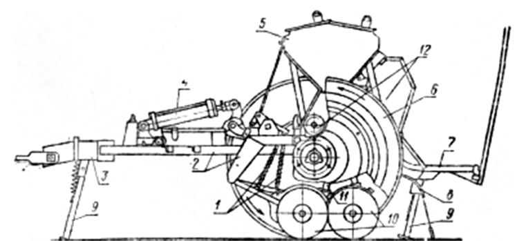
Workflow. The hopper of the SZ-3.6 drill has two compartments: the front one for seed, and the rear one for granulated fertilizer. The bottom of the front compartment has openings through which the seed enters the metering units attached to the bottom of the hopper. Metering units for fertilizer are installed on the rear wall of the hopper.
Furrow openers 10 are arranged in two rows at a distance of 15 cm from each other across the width of the machine. They are connected at the front to the opener beam by links. In addition, the furrow openers 10 are connected to the lifting square shaft forks by rods 1.
When the seed drill is in operation with the furrow openers engaged, the seed from the front compartment and fertilizer from the rear are fed by the metering units into the funnels of the seed tubes 11. Through the seed tubes, the seed and fertilizer flow by gravity into the mouths of the furrow openers 10 and then move along the guides to the bottom of the furrows opened by the openers. The seed is covered by soil crumbling from the furrow walls. Finally, the seed and fertilizer are covered by covering discs 8 installed behind the furrow openers. The metering units are driven by the support-drive wheels through a transmission system. The furrow openers are raised and lowered into transport and operating positions by a hydraulic cylinder 4 connected to the tractor's hydraulic system. For the operator tending the seed drill, a footboard 7 is attached to the frame. When stopped, the board is supported by a stand 9. SZ-type seed drills are equipped with devices to monitor the rotation of the metering unit shafts and the depth of the furrow openers, as well as a two-way communication system between the operator and the tractor driver. These devices are not included in the standard set of the seed drill and are supplied upon special request.
DESIGN OF THE MAIN ASSEMBLY UNITS OF ROW DRILLS Seed hoppers are mostly made of sheet steel and have a downward-tapering shape, which facilitates the free flow of seed to the metering units. The seed hopper is covered by two lids on top. In the SZ-3.6 drill, the hopper consists of two compartments (for seed and fertilizer), each closed by two lids. Each lid has a handle, locking latches, and latches to hold it in an open position. It is possible to use the entire volume of the hopper for seed only when sowing without fertilizer. To do this, the windows of the fertilizer metering units are closed with sliding shutters, and the dividers inserted inside the hopper are removed. Metering units. The uniformity of seed distribution in the field depends significantly on the quality of the metering unit performance. Fluted-roll metering units, which are installed on the main machines, have found wide practical application for the sowing of seed of grain crops and grasses. Despite some differences in the structural design of individual types, fluted-roll metering units operate on a single principle, and their main parts are standardized.
a – housing; b – roll; c – seed tube
Design of the fluted-roll metering unit
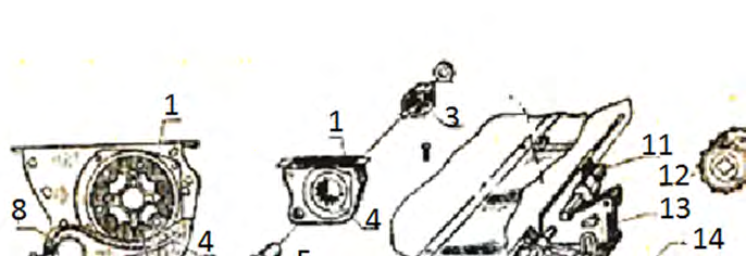
The fluted-roll metering unit consists of a housing 1, a fluted roll 5, a coupling 3, and a socket 4. The roll 5 is rigidly mounted on a shaft 7, and the coupling 3 is placed next to it. The axial movement of the roll and coupling relative to the shaft 7 is restricted by cotter pins. Along with the shaft, the roll can move axially within a wide range until it is fully pushed in (or pulled out) of the housing. Such units are called adjustable-roll units.
Design and operation of the metering unit
Moving the shaft changes the working length of the roll, i.e., the part of it that is inside the housing 1. Changing the working length of the roll adjusts the quantity of sown seed, which is used to calibrate the seed drill for a specified sowing rate.
The shafts, together with the rolls, are moved by a lever along a quadrant. The housing 1 is attached to the bottom of the seed hopper under the grain outlet.
A socket 4 is inserted into one of the side openings of the housing, and the coupling 3 enters the other. The fluted part of the roll 5 extends from the housing through the slots of the socket 4, with the latter separating the working part of the roll from the non-working part.
Seed tubes and furrow openers of the seed drill
The seed enters the necks of the furrow openers through the seed tubes. Corrugated seed tubes are used on row drills for sowing grain, grain legumes, and other agricultural crops. Corrugated rubber seed tubes are more reliable in operation. They are made of more durable rubber and do not lose their properties when the temperature changes from 0 to 30°.
| Seed tube state | Length |
| In the unextended state | about 35 cm |
| In the extended state | up to 70 cm |
Corrugated seed tubes are installed on SZ-3.6 type seed drills and their modifications. A mouthpiece is secured at the top of the seed tube 18 for connection to the unit, and a bracket 21 is secured at the bottom for connection to the furrow opener.
The furrow opener forms a furrow, deposits the seed supplied by the sowing mechanism through the seed tube, and covers the seed with soil. The quality of seed covering – placing seeds at the required depth and into moist soil layers – depends significantly on its performance.
Based on their design, furrow openers are divided into the following types:
- disc;
- hoe.
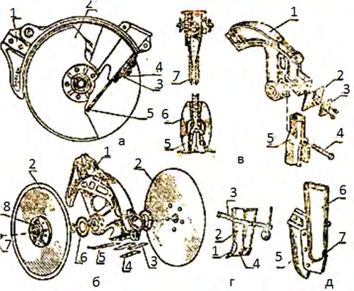
Figure 21 (a and b) shows the design of a disc furrow opener for the SZ-3.6 seed drill and some of its modifications. The base of the furrow opener is a cast housing 1 with flat discs 2. The discs are set at an angle of 10° to each other, forming a wedge that opens a furrow in the soil. Seeds enter the bottom of the furrow and are covered by crumbling moist soil.
The discs 2 are mounted in the housing on axles rotating in bearings, which are assembled within the disc caps 8. Rubber seals 6 are installed between the discs 2 and the housing, and cardboard gaskets are placed between the discs and the caps 8. Plugs 7 are screwed into the holes of the caps 8 to protect the bearings from soil and dirt. A guide 5 is fastened to the lower part of the housing funnel on the front furrow opener to direct seeds to the furrow bottom. A curved guide is installed on the housing of the rear furrow opener.
Mechanism for lifting and adjusting furrow opener depth
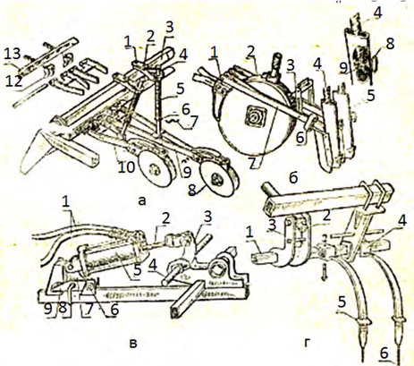
Disc furrow openers 8 of grain seed drills are connected via links 9 and 10 to a lifting shaft 11, which is mounted on the furrow opener beam 13 of the seed drill frame. The furrow opener links with the shafts are attached to the beam 13 using inserts 12 (SZ-3.6 seed drills).
Additional holes in the beam 13 are used when adjusting the furrow openers for different row spacings. To prevent the furrow openers from becoming clogged with soil, they are arranged in 2 or 3 rows: therefore, the links 10 of the front row furrow openers are shorter than the links 9 of the rear row furrow openers.
In older models of seed drills, the links are attached to the furrow opener beam in such a way that they can be moved along the beam by loosening the clamp fastenings.
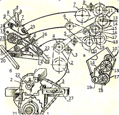
The furrow opener links are also connected to a mechanism for lifting and adjusting their working depth. This mechanism is designed as follows. A square lifting shaft 3 is mounted on the seed drill frame, to which rods 4 with springs 5 are connected via forks 2 and clamps 1. The lower ends of the rods 4 are connected by cotter pins to the furrow opener links so that the rod can move relative to the fork 2, overcoming the resistance of the spring 5. One end of the spring rests against the fork sleeve 2, and the other against a washer 6, held on the rod by a shaped cotter pin 7. By moving the cotter pin 7 into different holes on the rod 4, the compression of the spring 5 is adjusted, and consequently, the pressure on the furrow opener. Changing the spring compression levels out the path of individual furrow openers, most often those following the tracks of the tractor, seed drill, or hitch wheels. In the same way, the path of the front and rear furrow openers is aligned. The depth of the furrow opener path is set by a depth adjustment screw mounted on the frame rail of the seed drill (SZ-3.6). Screwing the screw in increases the furrow opener depth, while unscrewing it decreases it. In hydraulic seed drills, the furrow openers are raised to the transport position and lowered to the working position by an external hydraulic cylinder mounted on the seed drill frame and connected to the tractor's hydraulic system. In some older seed drill models, mechanical automatics are used to lift the furrow openers. The hydraulic cylinder 5 is pivotally connected to a bracket 7, which is linked by a pin 8 to a lever 9. The bracket 7, along with the lever 9, is pivotally connected to the frame drawbar by an axle 6. The hydraulic cylinder is connected to the tractor's hydraulic system via hoses 1. The hydraulic cylinder rod 2 is pivotally attached to the lever 3 of the front round lifting shaft 4, which is linked to the square shafts 3 of the furrow opener suspension. When oil is supplied to the hydraulic cylinder and the rod 2 retracts into the cylinder housing, the shaft 4 rotates and, through a system of levers, lowers the furrow openers into the working position. Transmission mechanisms. The shafts of the grain seed drill sowing mechanisms are driven by the machine's supporting/drive wheels through a system of gear-chain transmissions. Figure 23 shows a diagram and some components of the drive transmission mechanism for the SZ-3.6 seed drill and its main modifications. A sprocket 1 is mounted on the axle 21 of the supporting/drive wheel and is connected by a roller chain to a sprocket 2 on the countershaft 22. The gearbox allows for four gear ratios for the shaft 26 of the grain sowing units and six for the shaft 25 of the fertilizer sowing units. The four gear ratios for the transmission to shaft 26 are achieved by swapping gears 15, 17, 18, and 19. For sowing wheat and barley, the factory recommends installing gears with 17, 25, and 30 teeth, respectively, in the gearbox. In this case, the gear ratio from the supporting/drive wheel axle 21 to the sowing mechanism shaft will be 0.616. To sow oats, the gear ratio must be increased to 1.33. This is achieved by swapping gears 15 and 17.
and some components of the SZ-3.6 seed drill transmission mechanism
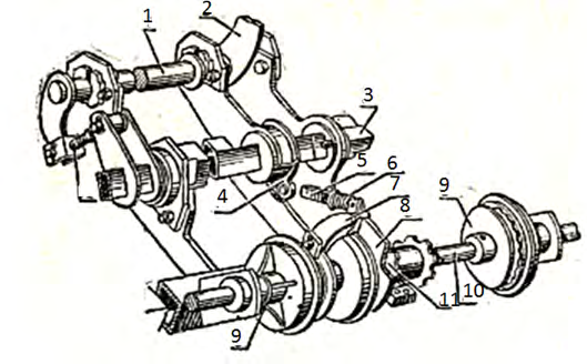
Disengaging mechanism. When the furrow openers are raised to the transport position, the transmission to the sowing mechanism shafts is disconnected, and it is engaged when they are lowered to the working position. The device for engaging and disengaging the transmission is mounted on the countershaft 10. On this shaft, the drive sprocket 11 only rotates when it is connected to the disengaging disc 8.
Automatic shut-off mechanism for the sowing unit
Disc 8 has a slot where the roller of lever 7 can enter. When the roller is in the disc slot, it releases the latch connecting sprocket 11 to the disc, and the transmission is disengaged.
When the hydraulic system is activated to raise the furrow openers, the process follows this sequence:
- the hydraulic cylinder rod rotates lever 2 of the lifting shaft 1 and the associated square shaft 3, to which the furrow openers are suspended;
- a crank 4 is fixed to shaft 3, connected to a spring-loaded (spring 6) rod 5;
- the rod, in turn, is connected to the disengaging lever 7;
- when square shaft 3 is rotated to lift the furrow openers, crank 4 turns the disengaging lever 7 via rod 5, the lever roller enters the slot of disc 8, releases the latch, and the transmission is disengaged.
Read next
Farm machinery For agronomists
Classification and design features of modern agricultural seeders
Farm machinery For agronomists
Technical maintenance and adjustment of seed drill sowing units
Farm machinery For agronomists