
Design and operating principle of the SUPN-8 pneumatic seed drill
7 min read
Purpose and technical specifications of SUPN-8
The SUPN-8 planter is designed for precision sowing of seed of corn, sunflower, and other row crops with simultaneous application of mineral fertilizer separate from the seed. The planter is designed for operation in all climatic zones except for mountain farming areas. It is coupled with class 1.4 tractors (MTZ, UMZ). It can be equipped with a monitoring system for the sowing process and the level of seed as well as fertilizer in the hoppers.
| Number of sections | Working width, m |
| 8 | 5.6 |
| 6 | 4.2 |
General design and operating principle of the planter
The operating principle of the planter is as follows. The rotation of the seed-metering discs and the spring augers of the fertilizer-metering units is carried out by the drive mechanism from the support-drive wheels. A vacuum in the horseshoe-shaped cavity of the metering unit cover is created either by a fan driven by a hydraulic motor from the tractor's hydraulic system or by suction created via a special pipe from the tractor's exhaust pipe. To control the vacuum level, a regulating valve with a diaphragm pressure gauge is installed on the fan or on the exhaust pipe to indicate pressure.
Sowing process:
- Seed is sucked onto the holes of the rotating disc located in the vacuum zone and transported from the intake chamber to the discharge zone.
- Excess seed sucked onto the holes is removed back into the intake chamber by the prongs of a fork installed in the unit's intake chamber, between which the seed attached to the holes pass during disc rotation.
- In the lower part of the unit, as the holes transition from the vacuum zone to the atmospheric pressure zone, the seed falls one by one from the hole and is placed on the bottom of the furrow formed by the opener's seed shoe.
- The spring augers of the fertilizer-metering unit with left-hand and first-pitch threading deliver fertilizer from the hopper into the funnels.
- The spreaders, performing oscillating movements at the outlet openings of the funnels, disperse the flow of fertilizer, ensuring a uniform stream into the fertilizer ducts, and then into the furrows formed by the fertilizer shoes of the openers.
- Coverers close the furrows containing the deposited seed and fertilizer with soil.
- Then, press wheels located behind the coverers compact the soil over the furrows, creating contact between the seed and the soil and conditions for moisture wicking.
- At the end, drags or a chain level the field surface and create a mulched soil layer.
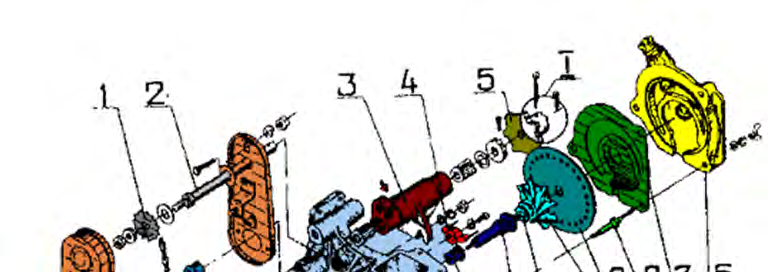
The seed metering unit consists of a cast housing 14 with an intake chamber and a cover 6, which has a vacuum chamber, between which a metering disc 9 with an agitator 10 and a gasket 7 are located. The metering disc is installed on the end of shaft 11, which rotates in nylon bushings 12. At the opposite end of the shaft, a sprocket 18 is installed on the flats and secured with a nut. Rotation is transmitted to the shaft by means of a chain drive of 37 links from the countershaft 2, which is installed in plain bearings and a bearing 3 secured in the upper part of the metering unit housing. The chain drive from shaft 2 to shaft 11 of the metering disc 9 is covered by a cover 19. A cotter pin 21 is provided at the end of shaft 2, designed to lock sprocket 5 in case the cotter pin 20 shears during operation.
The disc consists of a base and a thin metal plate, rigidly connected to each other. The base and the disc plate have holes located along a circle with a diameter of 120 mm, with the hole sizes in the plate being smaller than those in the disc base to prevent the holes from clogging.
Design and configuration of the metering unit
| 1 – 13-tooth sprocket | 2 – shaft | 3 – bearing |
| 4 – fork | 5 – sprocket 3.75 pitch–7 teeth | 6 – cover |
| 7 – gasket | 8 – stud | 9 – disc from the kit |
| 10 – agitator | 11 – shaft | 12 – bushing |
| 13 – cover | 14 – housing | 15 – housing |
| 16 – lever | 17 – flap | 18 – 16-tooth sprocket |
| 19 – cover | 20, 21 – cotter pin | 22 – washer |
In the unit, the metering disc is installed with the smaller diameter holes facing the seed intake chamber and the "VS" ("external side") marking facing the vacuum chamber of cover 6, and is pressed by the agitator 10 against the vacuum chamber of cover 6.
When sowing seed with an elongated embryonic part, attention must be paid to the correct installation of the metering disc with 5.5 mm diameter holes into the metering unit housing. For sowing such corn seed, as well as for very small sunflower seed, it is necessary to:
- take discs without holes;
- manually drill holes of the required diameter in them.
Burrs on the disc holes on the seed suction side are not permitted. If burrs are present, or if the number of holes is greater than 22, the vacuum will be insufficient to hold and transport the seed.
Adjusting the seed metering system
The vacuum chamber is a horseshoe-shaped plane that is connected via an air duct to the fan intake, or to the tractor pipe. The cover is fastened to the unit housing using studs 8. To remove excess seed attached to the holes of the metering disc back into the intake chamber, a fork 4 is installed in its upper part.
By rotating the fork around its own axis, the distance between its pins is changed relative to the circumference along which the holes of the sowing disc are located. The distance between the fork pins relative to the sowing disc is set in such a way that only one seed attached to the holes can pass between them. By adjusting the position of the fork, single-seed sowing of seeds of different sizes is ensured with a single disc.
The required position of the fork pins relative to the holes of the sowing disc is achieved using lever 16 along scale 15. Moving the lever relative to the scale by one division corresponds to a change in the distance between the fork pins by 1 mm. Lever 16 is fixed by tightening the wing nut.
Emptying the unit is carried out through an opening closed by cover 13. To check the suction of seeds to the holes of the sowing disc before sowing, an opening is provided in the housing of the unit, which is closed by shutter 17.
Design and operation of the transmission mechanism
The transmission mechanism consists of two cast side plates 8 and 12, connected to each other by three rods 4. Two hexagonal shafts are mounted in the side plates on ball bearings 1: input shaft 11 and output shaft 3.
A block of three sprockets is installed on the input shaft of the transmission mechanism, transmitting rotational motion via a chain (43 links) to a block of five sprockets 10 located on the output shaft. Both blocks can move freely along the shafts.
| Input shaft block (sprockets) | 12, 19, 21 |
| Output shaft block (sprockets) | 13, 15, 19, 23, 25 |
Bracket 7 with roller 6, mounted on a square shaft, is fixed in the extreme position by handle 2, which is also used to slacken the chain when moving it to the required sprockets of the blocks to change the gear ratio.
From the output shaft of the transmission mechanism, torque is transmitted by sprocket 4 via a drive chain (43 links) to the shafts of the counter-drives of the sowing units (for four), connected to each other by hinges. By means of sprocket 6, located on the input shaft of the transmission mechanism, torque is transmitted to the shaft (two shafts connected by a hinge) of the fertilizer application unit or units.
Design of the fertilizer application unit and markers
The fertilizer application unit is intended for applying a starter dose of mineral fertilizers and their mixtures in granular, powdery, and crystalline forms into rows during the sowing of crops. The unit consists of bracket 31, on which hopper 1 with lid 3 is mounted. The device includes:
- funnels 22 with ceramic-metal bushings 19 on the end walls of the hopper;
- shaft 25 with spring augers 13 and 29 in the lower part of the hopper;
- spreaders 14, fixed on bushings 15 of shaft 25 and located inside the funnels;
- deflectors 38, hingedly fixed to the walls of the hopper;
- two hatches in the bottom of the hopper, closed by pans 36 and secured with lock 1.
Markers of the disc type are intended for forming a trace of the unsown part of the field in order to obtain matching row spacings and ensure the straightness of the unit's movement during subsequent passes. Basically, lowering and raising the markers is carried out by a hydraulic mechanism controlled from the tractor cab, but in practice, either mechanical lifting is used, or the markers are adjusted so that they are lowered only at the beginning of sowing. Each marker has a rod with a stay, which are hingedly connected to a bracket fixed with bolts to the frame flanges. Axles are attached to the rods, on which the discs rotate freely.
Pneumatic seeder for seed placement with discs 4. The design of the seeder allows for its wide use regardless of the type of soil and the level of its preparation – traditional or minimum. Sowing using the double discs of the sowing unit allows the seeder to be used for many crops, providing high-quality placement even for small-seeded crops such as rapeseed.
Read next
Farm machinery For agronomists
Classification and design features of modern agricultural seeders
Farm machinery For agronomists
Technical maintenance and adjustment of seed drill sowing units
Farm machinery For agronomists