
Machinery and working parts for primary conservation tillage
6 min read
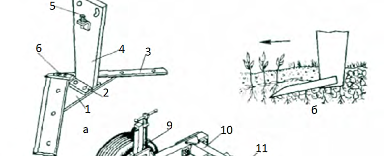
subsurface tillage Machines for primary subsurface tillage at a depth of 25–30 cm are equipped with arrow-shaped flat-cutting sweeps with a working width of 110 cm each. A heel 2 is welded to the lower end of the deep-ripping tine 4. A shoe with a chisel 6 and self-sharpening shares 3 is attached to the heel. An adjusting screw 5 is screwed into the angle welded to the tine on the frame side, with its head resting against the frame beam. Rotating the screw 5 changes the inclination angle of the sweep. An oval hole in the tine 4 allows it to pivot relative to the front bolt when the sweep angle is adjusted. The soil layer, cut by the share, slides along its inclined surface, gets loosened, and falls without being inverted.
a – arrow-shaped flat-cutting sweep; b – share; c – flat-cutter/deep-ripper
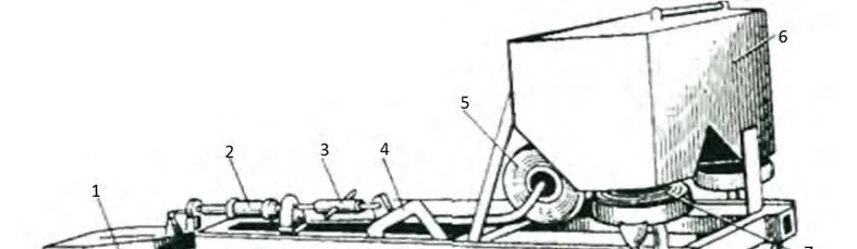
The PG-3-100 flat-cutter/deep-ripper is equipped with three flat-cutting sweeps 7, each with a working width of 110 cm. The angle between the cutting edges of the shares is 100°. The working width of the machine is 3.1 m, and the tillage depth is up to 30 cm. The latter is adjusted using a screw mechanism 9 by changing the mounting height of the gauge wheels 8. The PG-3-100 is aggregated with class 3 tractors. PG-2S and PG-3S flat-cutter/deep-rippers are equipped with two types of working tools: flat-cutting sweeps for subsurface tillage at a depth of up to 25 cm and chisel ripping tines (see "Chisel ploughs") for cutting slots and loosening the soil at a depth of up to 35 cm. The working width of the machines is 2.1 m and 3.1 m, respectively. They are aggregated with traction class 2 and 3 tractors. The NG-3-5 flat-cutter/deep-ripper consists of a central section and two side sections. The working width is 5 m, and the tillage depth is 15–30 cm. When working with class 3 tractors, only the middle section with a working width of 3.2 m is used. For subsurface tillage with stubble retention at a depth of up to 25 cm, PB-5 and PB-9 ripper-ploughs are used, as well as general-purpose ploughs equipped with subsurface bodies or ripping tines (see section 1.3 "Ploughs"). The KPG-2.2 cultivator/deep-ripper/fertilizer is equipped with two sweeps 14, each with a working width of 110 cm, a 450 L capacity hopper, fertilizer application units 7, and a fan 5.
1 – hitch device; 2 – hydraulic cylinder; 3 – depth regulator; 4 – half-shaft; 5 – fan; 6 – hopper; 7 – sowing unit; 8 – air duct; 9 – fertilizer duct; 10 – mixer; 11 – distributor; 12 – share; 13 – chisel; 14 – sweep; 15 – drive shaft; 16 – wheel; 17 – frame
The sowing units are driven by the gauge wheel 16 via a drive shaft 15 and a chain drive. A hydraulic motor rotates the fan wheel. The sweeps are equipped with a device for subsurface fertilizer application, including a mixer 10, a fertilizer duct 9, an air duct 8, and a distributor 11. When the fertilizer sweeps are lowered, the drive to the sowing units engages, and fertilizers enter the mixer through the fertilizer ducts. A stream of airflow created by the fan is fed through the air duct into the mixer, which picks up the fertilizer and carries it to the distributor. Fertilizers are distributed at the bottom of the furrow uniformly across the entire working width of the sweep. The soil falling off the shares covers them, and the exhaust air fills the space between the soil particles, with some of it escaping into the atmosphere. The cultivator is moved into working and transport positions by the hydraulic cylinder 2. The depth of tillage and fertilizer placement, ranging from 12 to 27 cm, is adjusted by rotating the turnbuckle of the regulator 3. The working width of the cultivator is 2.15 m, the operating speed is up to 10 km/h, and the productivity is 1.4 ha/h. It is aggregated with DT-75V and T-4A tractors. A hitch of two cultivators is aggregated with a K-701 tractor.
Test 1. Self-control tasks 1. By what criteria are ploughs classified? a) () by the number of working tools, by the method of aggregation with the tractor, by purpose; b) () by the method of ploughing, by purpose, by the method of aggregation with the tractor; c) () by the number of working tools, by purpose, by the type of mouldboards, by the number of skim ploughs; d) () by purpose, by the method of aggregation with the tractor, by the number of bodies, by the shape of the working surface. 2. The depth of soil tillage by the BDT-3 disk harrow is set by: a) () changing the position of gauge wheels using the depth adjustment mechanism; b) () changing the gang angle and the pressure of the disks on the soil; c) () changing the speed of the aggregate; d) () increasing the weight of the battery.
The figure of the Europal plough body (left) shows: a) () a root removal device; b) () a subsoiler; c) () a sub-surface ripper; d) () a chisel tine. 4. The point of the skim plough should be positioned mm above the point of the plough share. a) () 12–16 mm; b) () 8–15 mm; c) () 10–17 mm; d) () 14–18 mm. 5. Stubbing, harrowing, levelling, cultivation, rolling, hilling, ridging, etc. are… a) () primary tillage; b) () special tillage; c) () surface tillage; d) () shallow loosening. 6. The PLN-5-35 plough is intended for: a) () flat ploughing; b) () ridge-and-furrow ploughing; c) () subsurface ploughing; d) () chisel ploughing. 7. The numbers 1, 4, 6, 7, 10 indicate: a) () body, main beam, gauge wheel with depth adjustment mechanism, longitudinal beam, skim plough; b) () share, longitudinal beam, drive wheel, cross beam, skim plough; c) () mouldboard, cross beam, depth adjustment mechanism, main beam, body.
Plough hitching diagram for PLN-3-35: a) () two-point; b) () three-point; c) () front 9. The diagram shows the adjustment of … a) () plough frame; b) () plough hitch mechanism; c) () working width of the first body of the PLN-5-35 plough; d) () working width of the first body of the PLN-5-35 plough. 10. In the drawing of the Europal plough frame assembly (left), the mechanism is … a) () for stepwise adjustment of the working width of each body; b) () for mounting the plough body; c) () a safety device against plough body overload 11. For conservation tillage instead of autumn and spring ploughing, soil loosening on mouldboard and non-mouldboard backgrounds with deepening of the arable horizon, deep loosening of soil on slopes and fallow fields, the following is used: a) () deep ripper; b) () chisel plough; c) () reversible plough; d) () cultivator-deep ripper. 12. The numbers 2, 3, 5, 9, 12 indicate: a) () frame, disc gang, hydraulic cylinder, transport wheels, hitch; b) () beam, disc, leveling device, transport wheels, spoke; c) () frame, disc, hydraulic motor, hitch, gauge wheels
The drawing shows a deep ripper share; () sweep share; () chisel shank; () jointer.
AND PLANTING OF CROPS
Read next
Farm machinery For agronomists
Technical preparation and adjustment of a mounted plough for ploughing
Farm machinery For agronomists
Efficiency of chisel ploughs for deep soil loosening
Farm machinery For agronomists