
Classification and design of modern agricultural tractor ploughs
12 min read
They are classified by purpose, method of connection to the tractor, number of bodies, shape of the working surface, and other features. By purpose, plows are divided into general-purpose and special-purpose. The latter include:
- garden;
- forestry;
- vineyard;
- shrub-clearing;
- swamp, etc.
Tractor-mounted general-purpose plows are subdivided by their attachment method to the tractor into mounted, semi-mounted, and trailed. By the type of traction, plows are divided into tractor-drawn and those mounted on self-propelled chassis. By the design of the main working component, plows are divided into share and disc types. Share tractor plows are the most widely used. Based on the shape of the working surface of the bodies, share plows are available with cultural, semi-helical, and helical moldboards.
The working surfaces of plow bodies are right-turning; when plowing with such plows, ridge crowns or open furrows are formed. For level plowing without ridges and furrows, reversible plows are used, which are equipped with both right- and left-turning bodies.
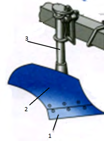
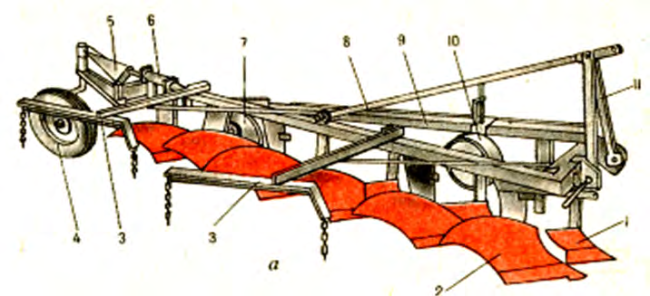
The five-body mounted plow PLN-5-35 for general purposes is aggregated with tractors of the 30 kN class. The main working components of the plow include: a body, skimmer, coulter, and subsoiler (installed to deepen the arable horizon). The body consists of a share 1, a moldboard 2, and a landside (not visible in figure 2). All these parts of the body are attached to the standard 3.
The skimmer, like the body, consists of a share and a moldboard mounted on a standard. The coulter is a disc type, intended for cutting stubble and leveling the edge of the furrow. On this plow, the coulter is installed before the last body. Auxiliary parts of the plow include: the frame, suspension, and a gauge wheel with a device for adjusting the plowing depth. The suspension of a mounted plow consists of an attachment mechanism (standard) and a brace.
The upper ends of the standards and the brace are connected by a common bolt. Two pins are welded to the brackets at the front of the frame. The rear hinges of the tractor's lower hitch links are placed onto these pins, and the top link is connected by a bolt to the upper end of the suspension. The gauge wheel is located on the left side of the plow; during operation, it rolls along the unplowed field and limits the penetration depth of the bodies. With screw 10, it can be set at various heights relative to the supporting plane of the bodies.
The plowing process proceeds as follows:
- As the plow moves, the coulter cuts the furrow slice in the direction of the plow's movement.
- The skimmer removes the upper de-structured and weed-infested layer of the furrow slice and drops it into the furrow opened by the previous body.
- The body share cuts the furrow slice from below, lifts it slightly, and transfers it to the moldboard.
- The moldboard turns and crumbles the furrow slice.
Since the furrow slice is turned to the right, the soil resistance tends to turn the plow to the left. To prevent this turn, a landside is installed on the body, which bears against the furrow wall. We will consider the design features of semi-mounted and trailed plows using the following implements as examples.
The semi-mounted plow PLP-6-35 connects to the tractor in the same way as the mounted one – using pins and a suspension. During transport, it rests on the rear wheel. During plowing, the rear wheel runs in the open furrow, and the front gauge wheel runs along the unplowed part of the field. The rear wheel is connected to the plow frame and the hydraulic cylinder rod by a four-link mechanism.
The working components of semi-mounted and trailed plows are interchangeable with those of mounted plows having the same cutting width. Design of plow working components. As already noted, the main working components of the plow include the body, skimmer, coulter, and subsoiler.
First, let's examine the design of the body's constituent parts. Shares of the bodies can be:
- trapezoidal;
- chisel-shaped;
- with a retractable chisel;
- with a welded cheek.
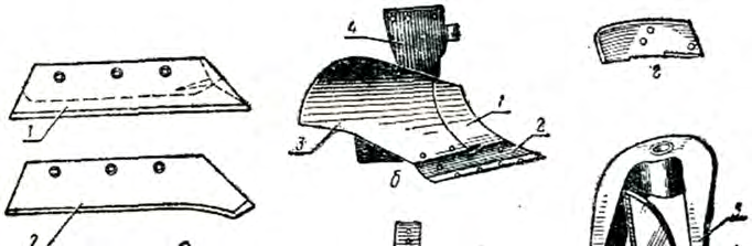
Trapezoidal shares are made in the shape of a trapezoid 1. To increase the service life of these shares, a thickening (metal reserve) is made on the underside, which allows the share to be drawn out and sharpened when the edge wears down.
Trapezoidal shares are usually made in two layers: the top layer of mild steel, and the bottom of a hard, wear-resistant sormite alloy. Due to uneven wear of the layers, the share remains sharp at all times. However, sormite is a brittle alloy and chips upon hitting stones.
| a – shares | b – moldboard | c – skimmer | d – jointer | e – disc coulter |
Chisel-shaped shares have a toe elongated into a chisel shape.
Shares with a welded cheek are intended for soils contaminated with stones.
Shares with a retractable chisel differ in that as they wear, the chisel can be extended, thereby prolonging their service life.
Triangular shares are used on helical bodies. Body moldboards can be cylindrical, cultural, semi-helical, and helical. Cultural and semi-helical moldboards are installed on general-purpose plows.
Cultural mouldboards (in combination with jointers) crumble the soil slice well and partially invert it. Ploughs with cultural mouldboards are used for working on sufficiently clean soils. When jointers are installed, such ploughs can also be used on slightly soddy soils. A mouldboard assembly with cultural mouldboards is fitted on all general-purpose ploughs.
Semi-helical mouldboards crumble the soil slice slightly worse than cultural ones, but invert it better. Therefore, semi-helical mouldboards are used when tilling (without a jointer) weed-infested and soddy soils. Sometimes, for better inversion of the slice, an extension is attached to the mouldboard.
Mouldboards are made of three-layer steel and subjected to heat treatment, which gives them wear resistance and elasticity. In the plough bodies of the PL family, the mouldboards are made in sections, with a replaceable breast 1. When worn, the breast is replaced with a new one. Thus, in these bodies, the working surface consists of three parts:
- share 2;
- mouldboard 3;
- breast 1.
The landside compensates for lateral reactions that occur during ploughing and prevents the plough from shifting to the side. The landsides are made of alloy steel, and the most wearable rear end (heel) is hardened. The landside of the rear body has a replaceable heel. For mounted plough bodies, the landsides are made wider than for trailed ones.
Body standards can be cast, stamped, or welded-stamped. Cast standards are cast from steel or high-strength cast iron. After casting, they are subjected to heat treatment. In the lower part, the standard has a saddle for installing and fastening the share and mouldboard. If the share has a retractable chisel, a groove is made for it in the standard.
The bodies of PL ploughs are made with stamped standards 4. On the land side, a groove is made in the standard for attaching the landside. The standard is bolted to the plough frame.
The jointer is installed in front of the plough body and is a small body with a working width equal to ⅔ of the main body's working width. The jointer consists of a steel standard 3 and a share 5 and mouldboard 4 attached to it with countersunk bolts. The jointer share is trapezoidal and is made of carbon steel. The share blade is heat-treated to a width of 20 to 25 mm. The mouldboard 4 is made of steel, case-hardened and quenched.
| Case-hardened layer thickness | from 1.0 to 1.5 mm |
With a holder 1 and a clamp 2, the jointer is attached to the plough frame at such a distance from the main body that the slice lifted by the main body passes freely and does not touch the jointer. Four holes are made in the jointer standard, and one in the holder. By placing the bolt in one of the holes of the standard and the holder, the position of the jointer is fixed by height.
On ploughs for soils infested with stones, instead of jointers, skimmers are installed, consisting of a mouldboard and a bent standard. The standard is attached to the beam of the main body with a clamp. The skimmer is installed so that its lower part fits tightly against the mouldboard of the main body.
During ploughing, the skimmer removes the upper part of the slice when it is in a raised position. The cut part of the slice is dumped by the skimmer to the bottom of the furrow. Skimmers installed directly on the main plough bodies for stony soils have less metal intensity and rise along with the body when it hits a stone. A separate safety device for the skimmer is not required.
Knives are designed to cut the sod layer. They are disc and coulter types. In most ploughs, the knife is installed only in front of the last body. For ploughs intended for ploughing virgin and fallow lands, knives are placed in front of each body. A disc knife consists of a steel disc 10 with a hub 1, mounted on two roller bearings 6. The bearings are seated on an axle fixed to a fork 5, which encloses the disc.
To protect the bearings from dust, an oil seal is pressed into the cap 9, consisting of a felt ring and a rubber lip seal 4, tightened by a spiral steel spring. The ring and the lip seal are placed in a metal housing. To reduce wear on the caps and hub ends, adjustment rings 7 are installed on the axle 8 between the hub and the cap 9. As they wear out, the adjustment rings are replaced with spare ones. Lubricant is fed into the hub cavity through a grease nipple screwed into the hub.
The fork 5 is fixed to the lower end of the standard and can rotate within 20° in either direction. The angle of rotation is limited by a special cutout in the slotted washer, which is put on the lower end of the standard and attaches the fork to it. Such a fork mounting ensures that the knife can accurately follow the turns of the plough when entering and leaving the furrow or in case of accidental bends in the furrow.
The standard is rigidly attached to the plough frame with special cast-iron linings, pads, and a steel bracket. Disk coulters are manufactured from sheet steel. The blade is heat-treated to a width of 75 mm. The disk is sharpened on both sides. The edge thickness must not exceed 0.5 mm.
Subsoilers are designed to deepen the arable soil layer. Deepening a shallow arable layer by simply setting the bodies deeper is not possible, as the subsoil brought to the surface reduces soil fertility. Therefore, the subsoil is loosened simultaneously with ploughing without being brought to the surface. Under the action of bacteria and fertilizer, the loosened arable layer gradually becomes fertile.
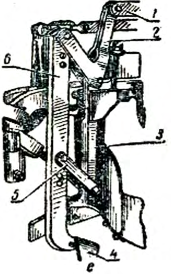
The subsoiler consists of a standard 6 with a share 4 at the end. The standard is attached to the riser 3 with a U-shaped link 2 and plates 5. As the plough moves, the share loosens the bottom of the furrow to a depth of up to 15 cm. The subsoiler standard 6 can be raised and lowered relative to the plough's support surface:
- Holes on the standard serve to regulate the operating depth of the subsoiler.
- The height position of the subsoilers relative to the plough bodies is changed by link 1.
- When link 1 is moved forward, the subsoiler rises relative to the body.
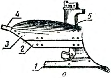
For working on podzolic soils with a shallow arable layer, cut-out bodies are used, which prevent bringing infertile podzol to the surface. Such a working tool consists of a lower chisel-type share 1, an upper share 2, a mouldboard 3 with a wing 4, and a standard 5. The lower share 1 crumbles the subsoil layer and passes it through the cutout without lifting it up. The upper share 2 and mouldboard 3 invert and pulverize the top layer, and the wing 4 helps to push it over effectively. Thanks to this design, the plough effectively incorporates organic and mineral fertilizers into the soil.
Deep loosening without soil inversion is performed using chisel bodies. They are equipped with specially shaped standards 1, the front side of which is protected by a steel plate 2, with contours repeating the chest of a standard cultural mouldboard. A second steel plate 4 is attached to the rear of the share 3. It lifts and further loosens the lower soil layer, which was previously cut by the share.
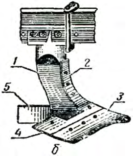
For stability of the implement's movement, the share 3 is installed at an increased angle to the furrow wall. Changing the geometry allows for complete overlapping of the joints between adjacent passes and the removal of split furrow marks. Furthermore, this position of the share reduces the tilting of the plough frame in the horizontal plane caused by side soil resistance forces.
- Installation angle of share 3 to the furrow wall — 70°
- Installation angle of a standard cultural body share — 42°
Design of the frame, gauge wheels, and plough hitch
Plough frames are manufactured from special frame and strip rolled steel, categorized into flat and hook types. Flat frames have gained the most widespread use; they are assembled from longitudinal beams 1 (their quantity corresponds to the number of bodies) and spacers 4. To reinforce the assembly, a rigid beam 2 is attached to the line of the bodies using clamps 3. In multi-body models, one or two rear beams can be removed to reduce the working width. On modern unified ploughs of the PL type, weldments without beam-mounted standards are increasingly used.
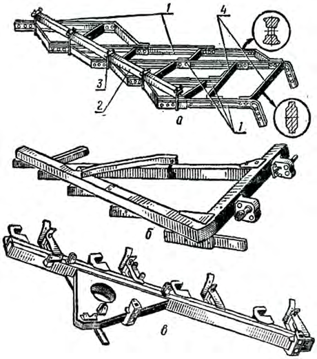
Standard frames are not suitable for tilling stony soils. In such conditions, it is necessary to work with the PKS-4-35 plough, which features a special welded frame made of rectangular pipes or paired channels, reinforced with angles and transverse spacers.
The ploughing depth of mounted ploughs is regulated by gauge wheels. The wheel rotates on a half-axle 5 in hub ball bearings 13, secured against axial displacement by a washer 1. The bearing assembly is protected from dust and dirt by a rubber frame seal 3, a washer 4, and a cap 15. The half-axle is welded to the standard 8, which is secured in the holder 7 and fixed to the plough frame 11 by bolts 6.
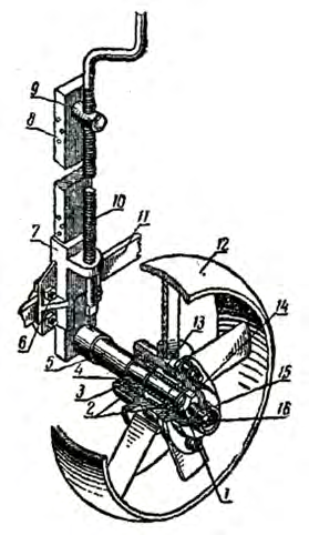
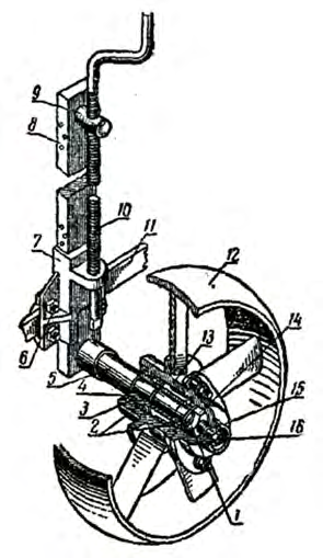
- Rotate the handle of the adjustment screw 10, secured in the holder by a shaped washer.
- The screw 10 moves the nut 9 installed in the upper part of the standard 8.
- The standard, along with the half-axle 5 and the wheel, rises or lowers, changing the position of the frame relative to the support surface.
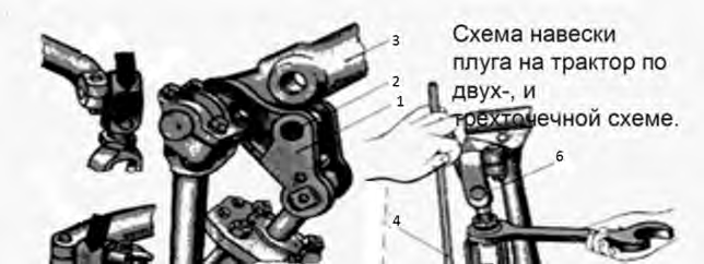
To aggregate the plough with a tractor, a two-point or three-point hitch scheme is used. In the three-point scheme, typical for working with MTZ-type tractors, the plough frame is connected to the tractor via a special suspension. The tractor's top link is attached to the plough's suspension yoke, and the left and right lower links are hinged to the bracket pins 5. The two-point scheme is used on DT-75-type tractors by shifting the tractor's lower links toward the center of the chassis and securing them to the central head of the hitch mechanism's lower axle.
The choice of hitching scheme directly depends on the tractor's running gear: for wheeled machines such as MTZ, a three-point plough hitch is used, while for tracked ones like DT-75, a two-point hitch is applied.
Read next
Farm machinery For agronomists
Technical preparation and adjustment of a mounted plough for ploughing
Farm machinery For agronomists
Design features and advantages of Lemken Europal reversible ploughs
Farm machinery For agronomists