
Technical preparation and adjustment of a mounted plough for ploughing
6 min read
The quality of ploughing directly depends on the correct preparation and adjustment of the mounted plough. Errors in adjusting the working bodies lead to uneven depth of tillage, increased fuel consumption, and accelerated wear of parts. For the mounted implement to operate efficiently, the machine operator must consistently perform a set of adjustment procedures on a level area and in the field.
Checking the correct assembly and technical condition of the plough should only be performed on a flat adjustment area. To do this, the plough is positioned so that its bottoms rest with their shares on the surface, and the frame is in a strictly horizontal position.
The system of measures for the technical preparation of the plough for operation includes four mandatory stages:
- checking the correct assembly and general technical condition;
- installation of working bodies on the plough;
- preparation of the tractor and mounting the implement;
- adjusting the unit for specific ploughing conditions.
Technology for setting and controlling working bodies
When assessing the plough geometry on the control area, the contact pattern of the shares with the surface is checked. Properly installed trapezoidal shares should fit against the surface along the entire length of the blade. Chisel shares should touch the support surface only with their points, while their right ends should be raised above the area by 10 mm. The share points and the heels of the landside plates must be strictly parallel and lie in the same plane.
The share blades of all bottoms must be parallel, and their points and right ends must lie on straight parallel lines. The planes of the landside edges of the bottoms must also be parallel to each other. In field conditions, these parameters are checked using a stretched string.
A deviation of the share points and their right ends from the line of the stretched string of no more than ±5 mm is permissible. Exceeding this value will lead to the plough skewing in the furrow and an increase in draft resistance.
- Height of the right ends of the chisel shares — 10 mm
- Permissible deviation of share points from the string — ±5 mm
- Distance from the skim plough point to the share point along the plough travel — 25–30 cm
- Height of the skim plough point 3 above the share point 4 — 10–17 mm
- Gap between the share point and the edge of the disc coulter 3 — 20–30 mm
Setting the working bodies begins with the arrangement of skim ploughs and the coulter. The skim ploughs are mounted on the frame so that the cut soil slices pass freely through the spaces between them and the main bottoms. The distance from the point of the skim plough share to the point of the main bottom share along the mounted plough travel must be 25–30 cm (or 250–300 mm).
To adjust the position of the plough share relative to the skim plough, follow these steps:
- Unscrew nut 5.
- Install or remove adjustment washer 2 to set the relative position of the bodies (the skim plough point 3 should be 10–17 mm higher than the plough share point 4, and the distance between them should be 250–300 mm).
- Tighten nut 5 and secure it with cam 1.
Installing the disc coulter is necessary to obtain a clean furrow edge. The distance between the share point and the edge of the disc coulter 3 should be 20–30 mm.
Adjusting the position of the disc coulter is performed according to the following scheme:
- Loosen castle nut 4.
- Move the coulter stand 5 relative to body 1 to set the required position of the disc coulter 3.
- Tighten castle nut 4 in the chosen position.
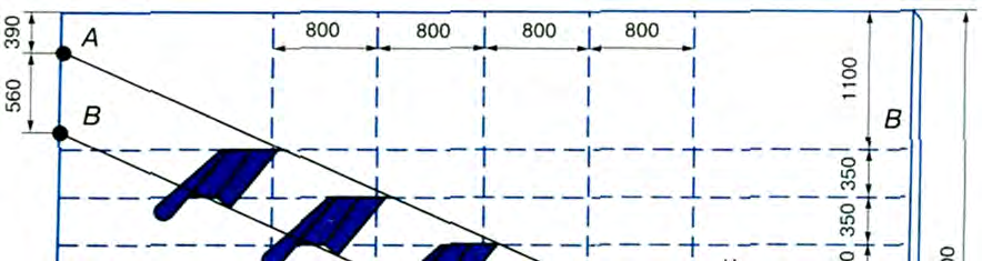
ADJUSTING THE CUTTING WIDTH OF THE MULTI-BOTTOM PLOUGH Technical requirements The cutting width of three-, four-, five-, and six-bottom ploughs should be 105, 140, 175, and 210 cm, respectively. Execution technology By rotating adjustment bolt 2, move the square axle 1 until the required cutting width is achieved. The landside edge of the skim plough must lie in the plane of the landside edge of the main bottom; a deviation towards the field of up to 15 mm is permissible. The blade of the skim plough share must be higher than the blade of the main bottom share: by 10 cm at a ploughing depth of 20 cm; by 12 cm at 22 cm; by 15 cm at 25 cm, and by 17 cm at a ploughing depth of 27 cm. The disc coulter is installed in front of the skim plough so that the disc is offset into the field from the left edge of the main bottom by 1–3 cm, and from the edge of the skim plough by 1 cm. The center of the disc is set above the point of the skim plough share; the lower point of the disc blade is 2–3 cm below its point. Preparation of the tractor and attaching the plough to it are essential for the stable travel of the ploughing unit and high quality of ploughing. Special attention must be paid to tractor preparation when working with mounted ploughs, and especially with a two-point mounting scheme. Before mounting the plough on the tractor, the tractor’s linkage mechanism and the plough suspension should be checked. If the tractor, for example DT-75, was operating with implements using a three-point linkage scheme, the system must be reconfigured to a two-point one before mounting the plough. To do this, the sleeve is secured on the lower axle so that it is offset 140 mm to the right from the longitudinal plane of symmetry of the tractor. The axle has a flat for securing the sleeve. The forks of the lower longitudinal links are disconnected from the side hinges and attached to the bracket of the sleeve. The front ends of the limiting chains are connected to the tractor lug forks, and the rear ones to the brackets of the lower longitudinal links. The trunnion sleeve of the upper adjustable linkage rod is mounted on the upper shaft so that it is in the same vertical plane as the sleeve. In this position, the sleeve is secured with stops on the upper shaft and the fork of the upper linkage rod is attached to it. The right and left vertical levers (braces) are installed to the right of the lift levers. To mount the plough, a DT-75 type tractor is reversed toward it so that the ball joints of the lower longitudinal linkage links can be put onto the plough suspension pins and secured with quick-release pins. Then, the upper rod is connected to the plough linkage upper rod and locked. The right brace is used to adjust the horizontality of the plough frame in the transverse plane; the length of the left brace must be constant and equal to 720–770 mm. The position of the plough frame in the longitudinal plane is adjusted by changing the length of the upper linkage rod. In the transport position, there should be a transport clearance of at least 250 mm under the first bottom. The length of the limiting chains is adjusted so that the ends of the lower longitudinal links have a lateral swing of no more than 20 mm in both directions. During ploughing, the limiting chains are loosened. When mounting a plough on a wheeled tractor like MTZ, the length of the left brace must be constant and equal to 515 mm. The horizontality of the plough frame in the transverse plane is adjusted by changing the length of the right brace: the braces are connected to the longitudinal linkage links with bolts inserted into the round holes of the braces. Adjusting the unit to the specified operating conditions primarily comes down to pre-setting the ploughing depth. The mounted plough is set to the specified ploughing depth in the following order: 1. The plough, mounted on the tractor, is placed on a level area so that all bottoms rest on it with their share points and landside plate heels. 2. By changing the length of the tractor's upper linkage rod and the braces, the plough frame is placed parallel to the area. 3. Shims are placed under the support wheel, the height of which corresponds to the specified ploughing depth, reduced by the depth of the wheel sinking into the soil (2–3 cm). 4. For the first pass of the plough in the field, the right linkage brace of the tractor is shortened so that the first bottom ploughs at half the specified depth. On the second pass of the plough, the right brace is used to eliminate the tilt of the frame in the transverse-vertical plane.
During operation, the ploughing depth is adjusted by repositioning the support wheel using a screw mechanism. When working with a mounted three-furrow plough, the tractor's right wheels run in the furrow, while the left wheels run on the field, i.e., higher than the right ones by a distance equal to the ploughing depth.
To set such a plough to a specified depth before heading out to the field, follow these steps:
- Place a wooden beam with a thickness equal to the ploughing depth on a level area and carefully drive the tractor's left wheels onto this beam.
- Then, lower the plough until the plough bodies touch the ground surface.
- In this tilted position of the tractor, adjust the plough's position in the horizontal and vertical planes.
- By operating the screws of the right lift rod and the top link of the mounting device, achieve a horizontal position of the plough frame in both transverse and longitudinal directions.
- Then, check the position of the plough hitch pin axis relative to the tractor's longitudinal axis.
It should be kept in mind that the final setup and adjustment of the plough to the specified ploughing depth and working width are carried out in the field while breaking in the plough during the first furrows.
Read next
Farm machinery For agronomists
Classification and design of modern agricultural tractor ploughs
Farm machinery For agronomists
Design features and advantages of Lemken Europal reversible ploughs
Farm machinery For agronomists