
Technological workflow and unit design of the Don 1500 combine harvester
38 min read
Technological process: the grain's path from field to hopper
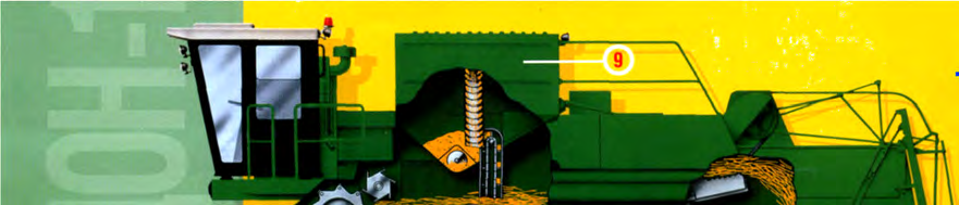
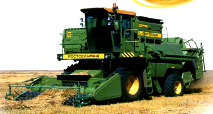
The technological process of the "Don-1500" combine is designed to harvest and clean grain as gently as possible while moving through the field. Failure to maintain proper settings at any stage inevitably leads to harvest losses in the straw or heavy contamination of the hopper with chaff. Understanding the trajectory of the plant mass helps the operator detect and eliminate malfunctions in the thresher and cleaning system in a timely manner.
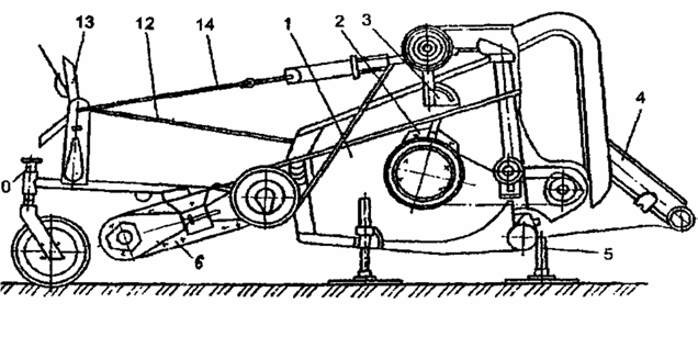
- Cutting and feeding: the slats of the rotating reel 1 submerge into the standing crop; the stems, cut by the cutting apparatus, are fed to the header auger 2, from where the finger mechanism directs the mass into the feeder house 3 toward the floating conveyor.
- Threshing: the lower branch of the conveyor directs the mass into the threshing apparatus 4, where the rotating drum hits the ears and drags them across the stationary concave, separating the main portion of the grain onto the grain pan 5.
- Chaff separation: the remaining straw and grain are thrown onto the beater, which reduces the flow speed and redirects the mass onto the straw walker racks 12 to separate the remaining grain.
- Air cleaning: the grain mix from the cleaning grain pan moves onto oscillating sieves, which are blown by the fan's 8 airflow to remove light impurities (chaff) into the chaff hood 13.
- Re-threshing: the cleaned grain falls through the lower sieve into the hopper, while unthreshed ears from the upper sieve extension are directed via the tailings auger 10 to the re-threshing device 11.
The separation and re-threshing systems work in close coordination, preventing grain from escaping into waste. For effective extraction of unthreshed ears, the combine is equipped with an adjustable upper sieve extension with transverse and longitudinal louvers. Large impurities (chaff and tailings) that do not pass through the louvers are discharged directly into the chaff hood 13 using a chaff spreader.
Header design and adjustment features
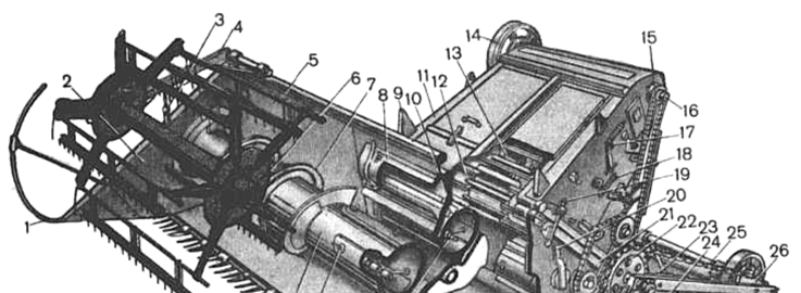
The header section of the combine is responsible for mowing or picking up crop mass and its uninterrupted delivery to the threshing apparatus. Structurally, this unit combines three elements: the header itself, the spacer with a beater, and the feeder house. The structural strength is provided by a frame assembled from a robust tubular beam, a front bar, and steel cross-braces.
To protect the mechanisms from external impacts and guide the flow, a wind shield 5, steel floor 40, side panels 2, and auger housing are attached to the frame. The passage of stems to the spacer beater goes through a technological window in the center of the wind shield. Depending on crop lodging and the type of crop being harvested, the header side panels are retrofitted with rod dividers 1 or special nose pieces.
| Scheme number | Header unit component |
|---|---|
| 1 | divider |
| 2 | side panel |
| 3, 34, 35 | hydraulic cylinders |
| 4, 24 | reel supports |
| 5 | wind shield |
| 6 | reel |
| 7, 41 | auger flights |
| 8 | header beam |
| 9 | stop |
| 10 | spacer beater |
| 11 | feeder house |
| 12 | conveyor driven shaft |
| 13 | floating conveyor |
| 14, 29 | pulleys |
| 15 | bearing |
| 16 | conveyor drive shaft |
| 17, 32 | levers |
| 18, 23, 30, 31 | adjustment screws |
| 19 | hook |
| 20 | spacer |
| 21 | transmission shaft |
| 22, 26, 38 | sprockets |
| 25 | chain |
| 27 | variator |
| 28 | rod |
| 33 | auger drive |
| 36 | linkage |
| 37 | knife drive mechanism |
| 39 | reel bearing |
| 40 | floor |
| 42 | cutting apparatus |
| 43 | auger finger mechanism |
| 44 | beater finger mechanism |
| 45 | finger |
| 46 | auger tube |
When harvesting short, tangled barley, be sure to remove the nose piece from the right side panel of the header. It is recommended to install torpedo-type dividers instead to prevent clogging of the cutting apparatus and reduce harvest losses.
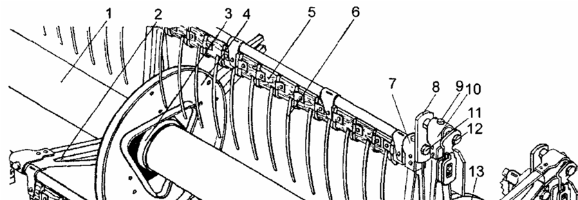
The reel is designed to separate a row of stems of the crop being harvested, guide them to the cutting apparatus, and feed the cut plants to the header auger. When harvesting tall-stemmed grains, it creates the necessary pressure to facilitate even feeding of the crop mass into the thresher. It consists of a central tube 1 with flanges 3 and support journals 17. Discs 4 with spokes 2 are attached to the flanges; at the ends of these spokes, in split bearings connected by a bracket 7, the rake tubes 5 are installed, equipped with spring teeth 6. On both sides of the reel, on the journals 17, eccentric mechanisms 15 are located. Thanks to the eccentric mechanisms, the rakes can assume different positions from plus 15° (tilted forward) to minus 30° (tilted backward) for operation in various conditions. The reel is mounted on two independent supports 4 and 24, located above the right and left side panels of the header. It rotates in two sleeve bearings 39, is raised and lowered by two synchronously acting hydraulic cylinders 3 and 35, and is extended by hydraulic cylinders 34 connected to double-armed levers 32 and linkages 36 fixed to the header side panels. Such a lever mechanism prevents the rakes from entering the cutting apparatus and header auger.
1 – central tube; 2 – reel spoke; 3 – flange; 4 – disc; 5 – rake; 6 – rake tooth; 7, 10 – bearing brackets; 8 – crank; 9 – bearing; 11 – pin; 12 – axis; 13 – carrier; 14 – roller axes; 15 – eccentric; 16 – driver; 17 – journal; 18 – ring; 19 – tension bolt; 20 – sprocket; 21 – hub; 22 – driven disc
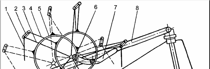
The reel is rotated by means of a V-belt variator 27 and a double-circuit chain drive consisting of sprockets 22, 26, 38 and bush-roller chains. A safety friction clutch is installed on the reel shaft. The eccentric mechanism ensures the specified rake inclination during reel rotation, changing automatically with the horizontal and vertical movements of the reel. It contains rake tubes 5, on which cranks 8 are fixed with axes 12 offset by 75 mm relative to the tube axes. The crank axes are installed in bearings 9 of the carrier rays 13 and secured with brackets 10. The carrier rests on three rollers installed on shafts 14 with its inner raceway.
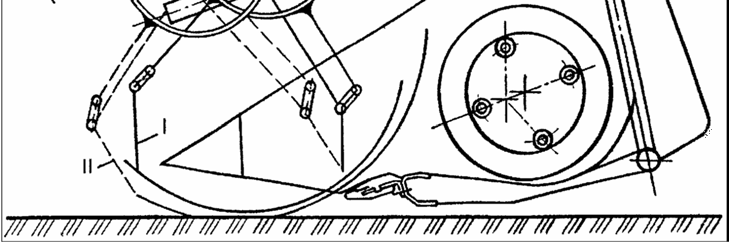
1 – finger; 2 – crank; 3 – reel ray; 4 – carrier ray; 5 – carrier raceway; 6 – roller; 7 – cam slot; 8 – reel support. Finger position: I – intermediate, II – corresponding to the maximum reel extension
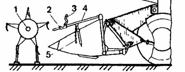
The reel is raised, the bearings are secured with covers 3, and the stands are removed and placed on the header body; after installation, the chain drive is fitted. The reel is dismantled in reverse order.
reel on stands: 1 – stand; 2 – reel ray; 3 – finger; 4 – quick-release cotter pin and reel removal: 1 – reel bearing; 2 – slider; 3 – reel bearing cover; 4 – reel support; 5 – safety chain
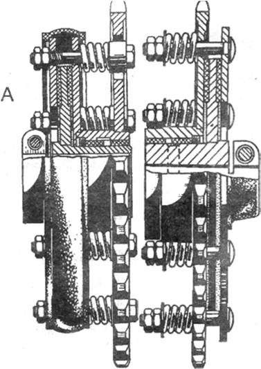
The reel variator consists of a drive pulley 7 and a driven pulley 9 connected by a V-belt 8. To ensure reliable variator operation, it is necessary that the pulleys be located in the same plane when the belt is in the middle position on the pulleys. Misalignment of the drive pulley relative to the driven one is eliminated using a tension screw and by rotating the support plate 3. The tension force of the variator belt is considered normal if its branch deflection is 8–10 mm at a force of 4 kgf. If the belt tension does not correspond to the specified values, move the belt so that it occupies the maximum diameter on the driven pulley, then, while rotating the nuts 7 with the variator running, achieve normal belt tension. Reel drive. A safety friction clutch 7 designed to transmit a torque of 60 kgf · m is installed on the left side of the reel shaft. The tension of chains 2 and 4 is adjusted by rotating the rod 1 and the tension screw 3.
1 – adjustable rod; 2, 4 – chain drive; 3 – tension screw; 5 – hydraulic cylinder for reel lifting; 6 – hydraulic cylinder for horizontal reel movement; 7 – safety clutch
The cutting apparatus is designed to cut the stems of the harvested crop at a specified height. Cutting apparatuses of various designs—with double fingers or open-type fingers—can be installed on the combine header. The pitch of the fingers and sections in both cases is 76.2 mm, the knife stroke is 88 mm, and the knife performs 473 double strokes per minute. The cutting apparatus consists of a knife and a finger bar 3 fixed to the front beam of the header. The knife receives reciprocating motion under the action of a wobble drive mechanism. The knife consists of a back 4 made of steel strip and sections 2 riveted to it, the blades of which have an upper sickle-shaped serration. The left part of the knife back is reinforced with a second steel strip, and a knife head 8 equipped with a ball joint is attached to it with rivets. The knife head guide 18 is secured to its back with rivets and moves in the slots of bracket 19 installed on the header front beam.
1 – finger; 2 – section; 3 – finger bar; 4 – knife back; 5 – hold-down; 6 – shim; 7 – friction plate; 8 – knife head; 9 – lever; 10 – output shaft; 11 – drive shaft; 12 – housing; 13 – finger; 14 – breather; 15 – wobble plate; 16 – flywheel pulley; 17 – cheeks; 18 – knife head guide; 19 – bracket; 20 – finger liner; 21 – finger bar; 22 – bolt; 23 – insert
The finger bar 21 is made of a special angle iron. Forged fingers 1 are secured to it with bolts 22, to which counter-cutting inserts 23 are riveted. The side surfaces of the inserts have a lower serration. Bolts 22 also fasten friction plates 7, hold-downs 5, and adjustment shims. Hold-downs are installed over every pair of fingers. The spherical joint of the knife head 8 is connected by cheeks 17, tightened through a spring with a bolt, to the joint of lever 9 of the wobble drive mechanism.
The wobble drive mechanism consists of a housing 7, a flywheel pulley 9, a drive (crank) shaft 8, a carrier (wobble plate) 3, an input shaft 1, and a lever 2 having a removable head 12. The drive shaft 8 is kinematically connected to the input shaft 1 by means of a bearing 4, carrier 3, and pins 6.
1 – input shaft; 2 – lever; 3 – carrier; 4 – bearing; 5 – pin; 6 – breather; 7 – housing; 8 – drive shaft; 9 – flywheel pulley; 10 – drain plug; 11 – oil level check plug; 12 – lever head; 13 – nut; 14 – cotter pin
When shaft 8 rotates, the carrier 3 performs an oscillatory motion, which is transmitted through pins 5 to the fork of shaft 1 and the head 12 of the lever, pivotally connected via cheeks. With the movable knife head. The drive mechanism of the cutting apparatus knife receives rotation via a V-belt drive from the counter-drive shaft of the header. The deflection of the belt branch at normal tension should be 12–14 mm at a force of 4 kgf. To ensure reliable operation of the cutting apparatus and knife drive during the operational break-in period of a new header (first 30 hours of operation), every 8–10 hours it is necessary: 1. Check the clearances between the knife head 9 and hold-downs 3 and 6. The knife must move freely in the guides; however, the total clearance at points B and E, C and D must be no more than 1 mm. Perform adjustment in the front part by installing shims 2, and in the rear by moving hold-down 6 along the slots of the oval holes.
Check the clearances between the knife head and the friction plate. The plate must not impede the free movement of the knife, but the total end play at the GiZh points must not exceed 1.5 mm. 3. Check the reliability of the mounting of the wobble box mechanism to the plate and the front upright of the header frame, the tightening of the lever fastening nuts on the wobble box shaft, the pulley-flywheel on the wobble box shaft, and the pulley-flywheel on the drive shaft. The same operations should be performed every 240 operating hours of the header or before the start of each harvesting season. The header auger is designed to transport the cut crop mass to the center of the header and feed it into the adapter. It consists of a cylindrical housing 4 with spiral ribbons of left 5 and right 21 hand directions welded to it.
1 – drive sprocket with a safety clutch; 2 – adjusting bolt; 3 – auger trunnion; 4 – cylindrical housing; 5, 21 – spiral ribbons; 6 – plug; 7 – washer; 8 – cheek; 9 – finger mechanism; 10 – axle; 11 – finger bushing; 12 – finger; 13 – quick-release cotter pin; 14, 28 – support plates; 15 – bushing; 16 – handle mounting bolt; 17 – handle; 18, 24 – finger mechanism trunnions; 19 – discs; 20 – hole for access to the grease nipple; 22 – eyelet; 23 – cage; 25 – ball bearing; 26, 29 – bolts; 27 – locking wire; 30 – bearing
In the center of the housing, opposite the wind shield opening of the header, is a four-row finger mechanism 9. A trunnion 3 is installed on the left end, resting on a bearing 30, which is fixed to the support plate 28. A drive sprocket 1 with a safety friction clutch is rigidly mounted on the trunnion. In the lower and rear parts, the auger is enclosed by the trough-shaped skin of the header housing.
On the right end of the trunnion 18, a bushing 15 is installed on a key, which has a handle 17 and is attached to the plate 14 with bolts. Bushings 11 with fingers 12 are put on the tubular axle 10; these fingers protrude from the auger housing 4 through plastic eyelets 22. The eyelets, which act as bearings and guides, are installed in cages 23, which are fixed to the auger housing.
When the auger rotates, the fingers 12 with bushings, driven by the eyelets 22, rotate on the stationary axle 10. Since the axle 10 is offset forward relative to the auger's center of rotation, the following processes occur:
- fingers on the front side of the auger protrude from the housing;
- on the rear side, the fingers retract;
- the auger finger mechanism actively captures the cut stalks in the front part of the auger;
- as they move toward the adapter, the fingers release the stalks.
The position of the auger relative to the header housing is adjustable. For this purpose, the housing of the left support bearing 30 and the bushing 15 (right side) are mounted on plates 28 and 14, which are held on the header housing by adjusting bolts 2 and four bolts 29. A hatch is provided in the left side of the header for installing and removing the auger. The auger is driven by a chain transmission from the header counter-drive shaft.
The adapter 20 serves as an intermediate link between the header and the feeder house. When the header is disconnected from the combine, the adapter always remains with the header. This significantly simplifies the assembly process of the harvesting unit without disturbing the position of the sealing elements between the header and the adapter or the settings of the balancing mechanism. The beater, located in the adapter, improves the flow of the crop mass from the header auger to the inclined conveyor.
The adapter consists of a housing 5 and an intermediate beater 4. The adapter housing has a welded frame to which the side walls and the bottom are welded. The housing also has:
- trunnions 7 with eyes for attaching the balancing mechanism hangers;
- hooks for attaching the adapter to the feeder house;
- a central spherical joint 13 for mounting the header.
Inside the adapter, there is an intermediate beater 4, equipped with a finger mechanism 1, the design of which is similar to the header auger finger mechanism. To improve the transport capacity of the adapter, there are combs on the beater casing.
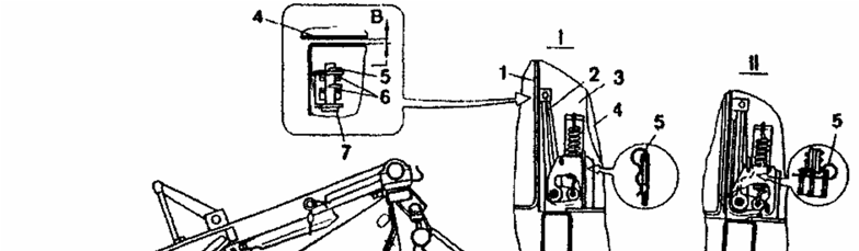
To prevent grain from spilling through the gaps between the header and the adapter at the joints, side shields and a transition sealing shield are installed. Side shields 3 are located on both sides of the adapter and, under the action of spring-loaded levers 2 installed on axles 7, they press simultaneously against the rear wall of the header skin and the side walls of the adapter housing. The shields can be set to a non-working position, which is necessary when disconnecting the header from the adapter. To do this, the levers 2 are fixed with cotter pins 5 in the bracket holes.
| 1 | finger mechanism |
| 2 | finger mechanism control shaft |
| 3 | counter-drive |
| 4 | beater |
| 5 | housing |
| 6 | finger mechanism clearance adjustment handle |
| 7 | trunnion with eyes |
| 1 | housing skin |
| 2 | lever |
| 3 | shield |
| 4 | adapter side wall |
| 5 | quick-release cotter pin |
| 6 | adjusting washer |
| 7 | axle |
| I | shield in working position |
| II | shield in non-working position |
| В | clearance between the shield and the header housing skin |
The beater is rotated from the feeder house transmission shaft through a safety friction clutch. The clearance between the adapter beater fingers and the housing bottom is adjusted to ensure efficient operation:
| Harvesting conditions | Gap, mm |
| Average | 28–35 |
When harvesting long-straw crops, it is increased, and for short-straw crops, it is decreased. The gap is adjusted by turning the adjustment lever 3. Turning clockwise increases the gap, while counter-clockwise decreases it.
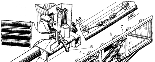
The header balancing mechanism consists of two lever-spring systems located on the header housing on both its sides. The base of each system consists of:
- spring block 2 and 6;
- lever 11;
- adapter link 13;
- suspension 4 or 10;
- removable pins 5.
The suspension of the right-hand spring system is adjustable. This is necessary for leveling the header housing when mounting it to the feeder house. The number of springs in the left and right blocks varies and depends on the mass and cutting width of the header.
The header housing is additionally connected to the adapter by transverse spring ties 3 and is articulated to the adapter. In combination with the balancing mechanisms, the housing has the ability to move in longitudinal and transverse directions. In the longitudinal direction, the movement of the housing is limited by stops, and in the transverse direction, by rollers interacting with the stops.
The feeder house consists of a housing, an upper drive shaft 16, a lower driven shaft 24, and a chain-slat conveyor 2. The hook 5 and tension screws 22 are intended for connecting the feeder house to the adapter.
Stops 6 and brackets 11 and 23 are rigidly attached to the feeder house housing. Inside the housing (in its upper part) there is a stiffening pipe 15 welded to the sides of the housing. Two covers 9, which provide access to the working elements of the feeder house, are articulated to the upper part of the housing. Lever 2, articulated to axle 1, is suspended from brackets 5 of the feeder house housing 12 using bolts 3. A spring 4 is installed between lever 2 and bracket 5.
a – suspension; b – incorrect position of nut 10; 1 – axle; 2 – suspension lever; 3 – suspension bolt; 4 – vertical suspension spring; 5 – suspension bracket; 6 – longitudinal suspension bolt; 7 – nut for adjusting spring tension; 8 – longitudinal suspension spring; 9 – bracket; 10 – nut with sleeve; 11 – limiting stop; 12 – feeder house housing; 13 – plate
With an increase in uneven delivery of the crop mass to the conveyor, the lower shaft rises, overcoming the pressure of the springs 4. At the same time, the lever 2 rotates around the axle 1. With further movement, the layer of crop mass tends to lift the lower branches of the conveyor chains, creating additional tension in the chains, which can reach high values. To reduce the loads arising under these conditions, an elastic support on the feeder house housing, having the following design, has been introduced.
Axle 1 can shift in the direction of chain tension in the oval slots of the sides of the feeder house housing 12. In the initial position, it is held by spring 8. The compression force of the spring is transmitted to the axle by bolt 6. The front end of the bolt is articulated to axle 1, and the rear threaded end enters bracket 9, against which spring 8 rests.
The compression of the longitudinal suspension spring is regulated by nut 7, screwed onto bolt 6. To relieve the conveyor chains from constant tension by springs 8, a special nut 10 is screwed onto the threaded end of bolt 6, resting on bracket 9 from the opposite side. This nut has a long sleeve, the purpose of which is to protect the threads of bolt 6 from damage during longitudinal movements in bracket 9.
Stop 11 limits the movement of the lower shaft due to chain tension. Under the action of additional forces arising in the conveyor chains during uneven mass delivery, the shaft, overcoming the pressure of springs 8, shifts in the direction of chain tension, and axle 1 moves along the slot.
Feeder house setup and drive adjustment
The feeder house is responsible for the stable delivery of crop mass from the header to the threshing unit. The productivity of the combine and the amount of grain losses behind the header directly depend on the accuracy of its settings. The operator should pay special attention to the conveyor tension and the adjustment of the gaps of the working elements. This prevents the house from clogging and premature wear of the chains.
- Conveyor tension spring length — 90 ± 5 mm
- Gap between the combs and the bottom — 5–10 mm
- Pressing slide gap — 5–12 mm
- Adjustable drive rod length — 460 mm
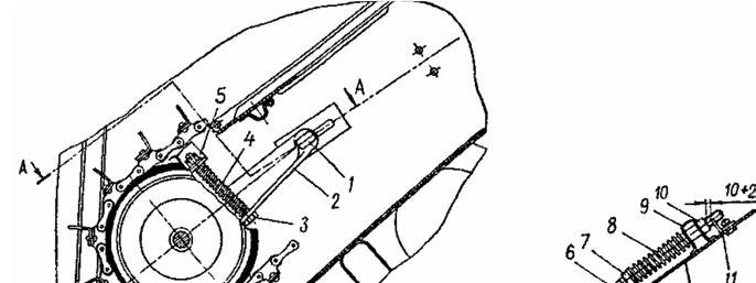
The tension of the feeder house chains is adjusted by moving the lower shaft. To do this, loosen locknut 10 and turn adjustment nut 7, compressing spring 8 to the required length. The gap between the combs and the bottom is set by changing the number of adjustment washers between bracket 5 and the block nut 3. The position of the pressing slides above the conveyor slats is corrected using adjustment bolts 12, against which the slide levers 10 rest.
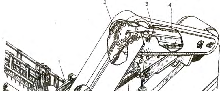
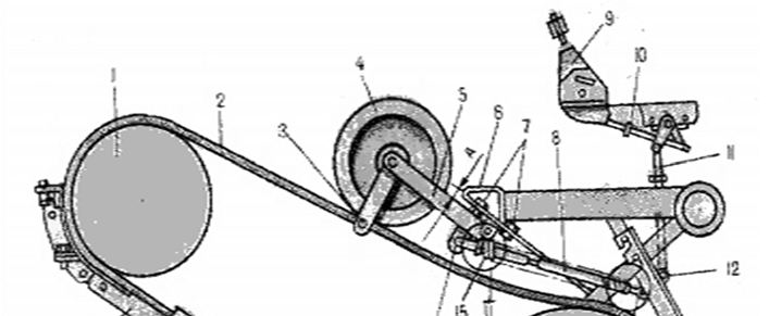
Engaging the feeder house drive is performed via the V-belt transmission tension pulley. When adjusting the mechanism, first set gap B to 10 mm between the faces of plug 16 and axle 3 using nut 17. Next, set distance C (460 mm) between the centers of the holes of the adjustable rod 8. In the final stage, with the mechanism engaged, adjust gap A, which should be 12 mm between bracket 6 and lever 5. In the engaged state, the gaps between the belt and guards 13 and 18 should not exceed 5 mm, and the distance to guard 20 should be within 6–10 mm.
Maintaining the engine speed when engaging and disengaging the drive prevents sharp dynamic shocks and extends the service life of V-belts.
| Engine operation mode during drive switching | Crankshaft speed limit, rpm |
|---|---|
| Standard operation | No more than 1000 |
| Emergency cases | No more than 1500 |
Operating the reversing mechanism and choosing header dividers
When harvesting weedy or damp crops, the working components of the feeder house can become clogged with straw mass. To clear them quickly without manual labor, the combine is equipped with a hydraulically operated reversing mechanism. It is mounted on the feeder house transmission shaft and allows the conveyor to be forcibly rotated in reverse. Improper use of this unit can damage the feeder house, so it is important to strictly follow the sequence of operations.
Improper use of the reversing ratchet mechanism or attempting to activate it while the header drive is engaged will guaranteed result in damage to the feeder house.
- Completely disengage the combine header drive.
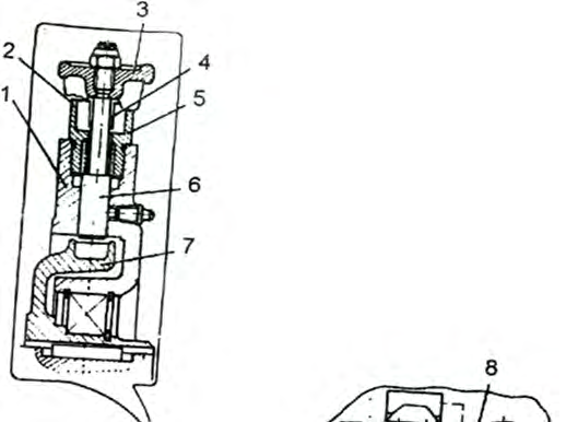
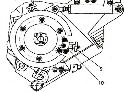
- Pull and rotate handwheels 3 and 9 so that they enter the deep slots 4 of the bushing, allowing the spring-loaded latches 6 to engage with the ratchet 7.
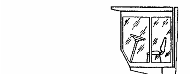
- Using the two control panel buttons on the right outer side member of the cab, alternately activate the hydraulic cylinder 8 for forward and reverse movement to rotate the working components.
- After the clogging is cleared, return handwheels 3 and 9 to the shallow slots 2 of the bushing to disengage the latches from the ratchet.
Torque is transmitted to the header working components through a system of sequential chain and V-belt drives. Any deviation in the alignment or tension of these drives leads to premature wear of the drive elements. The complete torque transmission scheme from the upper shaft of the feeder house to the header units is shown in the table.
| Drive shaft | Driven shaft |
|---|---|
| Upper shaft 9 of the feeder house | Transmission shaft 7 |
| Transmission shaft 7 | Counter-drive shaft 12 |
| Counter-drive shaft 12 | Header drive shaft 13 |
| Header drive shaft 13 | Reel variator drive shaft 4 |
| Reel variator shaft 2 | Reel counter-drive shaft 20 |
| Reel counter-drive shaft 20 | Reel shaft 18 |
| Header drive shaft 13 | Auger shaft 15 |
| Transmission shaft 7 | Spacer beater shaft 11 |
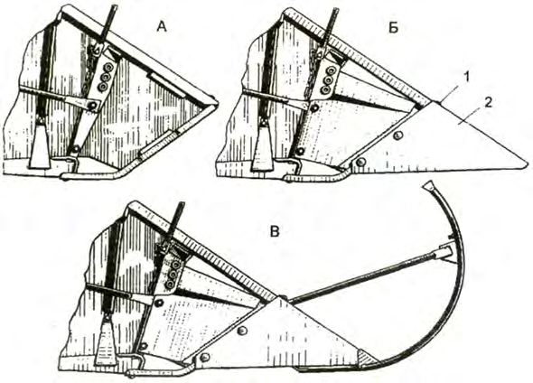
To reduce grain losses, the header must be adapted to the condition of the harvested crop. Depending on lodging, density, and height of the stand, different types of dividers are used. In clean, upright crops, operation without additional attachments is permitted — in this case, the side wall of the header itself acts as a divider. When working conditions become more difficult, special points are attached to the side walls, and rod or adjustable stalk deflectors are installed.
- Points 2, fastened to the header side walls with bolts 1;
- Rod dividers for clean, long-stemmed crops;
- Standard dividers equipped with adjustable stalk deflectors.
Upgrading header and feeder house units
Modernization of the "Don-1500" combine mechanical units is aimed at increasing their reliability in field conditions and simplifying daily maintenance. Designers have eliminated the mechanism for synchronizing reel movement relative to the cutter bar. The rods of the horizontal movement hydraulic cylinders have become longer and now connect directly to the sliders, which facilitates adjustment.
- Reel forward reach — 640 mm
- Reel backward reach — 250 mm
- Increase in conveyor shaft — by 5 mm
- Drive pulley grooves for the upper shaft — 4 pcs.
The cutter bar has received a more robust connection between the wobble box lever head and the knife using two flat plates and pins with spherical bushings. In the wobble box mechanism itself, the output shaft diameter and bearing size have been increased, and the needle bearings in the lugs have been replaced with wear-resistant bronze bushings. Additional pins for mounting the wobble box cover securely lock the unit under peak field loads.
In the header spacer, the combs in the finger outlet zone have been removed, and the finger bushings of the auger and spacer have received nylon elements. In the feeder house, the diameter of the upper shaft of the floating conveyor has been increased. New four-groove pulleys prevent drive belt slippage, and the removal of the lower pressure runners significantly reduces chain wear.
Nylon inserts in the auger and spacer finger bushings do not require lubrication during operation, which reduces the time spent preparing the combine for a shift.
Pickup platform for two-phase harvesting
Increased crop humidity and unstable weather delay harvesting and lead to grain losses. In difficult climatic conditions, switching to a two-phase method protects the harvest from shedding, extending operating time by 4–5 weeks.
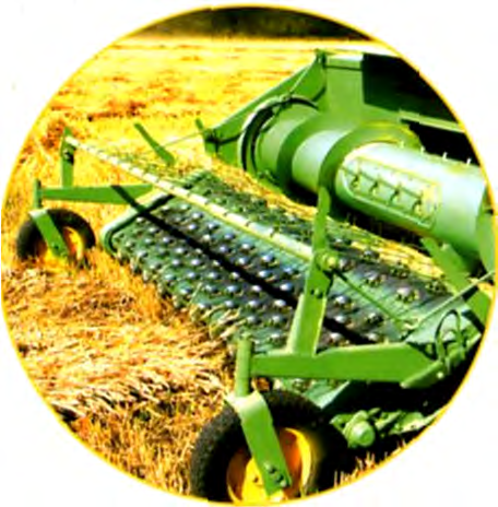
In separate harvesting, "Don" combines operate according to two aggregation schemes. Pickups are mounted either on a special 4 m wide platform or on a converted header with a 6 m cutting width. For working with double windrows formed by reversing headers from a 12–20 m strip, a universal pickup with a continuous belt-and-finger conveyor on a 4-meter platform is most effective.
The pick-up conveyor is pivotally mounted to the platform and rests on two self-aligning wheels. This allows the side panels to move independently, following the field terrain in both longitudinal and transverse directions. A crop guide (normalizer) with rake grilles positioned above prevents the wind from scattering the windrow and ensures an even feed of the crop mass into the feeder house.
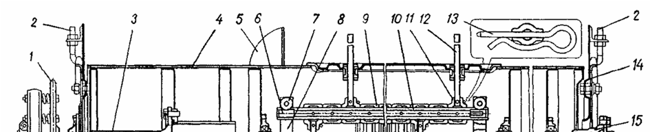
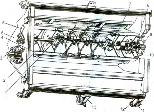
The core of the pick-up is the main frame, the casing of which protects the auger from the wind. Traction is transmitted to the rubberized fabric belt via chains from the drive shaft sprockets, and the pick-up fingers are secured in holders by spring clips. The complete list of components for the pick-up platform is provided in the table below.
| Diagram Number | Component or Part Name |
|---|---|
| 1 | Main platform frame (serves as a housing and wind shield) |
| 2 | Auger suspension brackets |
| 3 | Tensioner pulley mounting bracket |
| 4 | Spacer (rigidly fixed to the platform) |
| 5 | Screw jack |
| 6 | Canvas-finger conveyor assembly |
| 7 | Right support wheel |
| 8 | Conveyor belt |
| 9 | Left support wheel |
| 10 | Spacer sleeve |
| 11 | Stripper |
| 12 | Crop guide (rake grille) |
| 13 | Suspension lever |
| 14 | Unloading device |
Technological Process and Adjustment of the Pick-Up Platform
The pick-up efficiently collects crop mass from the windrow and transfers it to the combine thresher without loss. To increase the conveyor's impact on the straw, a crop guide (12) is installed above the belt. It consists of a grille made of a tubular beam with elastic tines. The ends of the beam are equipped with eccentrics acted upon by the linkages of the unloading device (14), creating pressure in the upper part of the conveyor.
The crop guide, in combination with the unloading device, allows for effective pressing of the collected mass with the tines. This ensures uniform feeding of stems to the auger without bunching or clogging at the intake.
The movement of the crop mass from the stubble to the feeder house follows a strictly defined algorithm. The coordinated operation of all elements guarantees minimal grain losses even when working with uneven windrows. The entire technological process is divided into sequential stages.
- As the combine moves, the windrow is directed into the center part of the pick-up.
- The spring tines (1) of the belt conveyor (2) comb the stubble from below and lift the crop mass from under the windrow onto the conveyor.
- The crop guide (3) presses the mass against the upper part of the conveyor and directs it with pressure toward the platform auger (7).
- When the belt wraps around the drive shaft (4), the tines rotate sharply, release the straw, and are cleaned by the active stripper (5).
- The slide board (6) of the stripper, oscillating at the shaft rotation frequency, feeds the stripped stems and loose grain to the auger (7).
- The auger (7), with its counter-directional spirals, moves the crop mass to the window in the center of the platform.
- The auger's finger mechanism grabs the mass and feeds it to the beater (9), from where the feeder house's floating conveyor directs it into the thresher.
To prevent the accumulation of fine particles on the platform floor and their dragging by the return branch of the conveyor, monitor the condition of the stripper (5). Its elastic working edge made of rubberized belts must constantly and tightly interact with the pick-up fingers.
The ground pressure of the pick-up's gauge wheels is adjusted using the unloading device (11). It consists of two tension spring linkages that connect the crop guide trunnions to the wind shield beam. This reduces the mechanical load on the soil and protects the gauge wheels from damage when operating on uneven terrain.
| Diagram Number | Pick-Up Platform Component Name |
|---|---|
| 1 | Tine |
| 2 | Belt conveyor |
| 3 | Crop guide |
| 4 | Drive shaft |
| 5 | Active stripper |
| 6 | Stripper slide board |
| 7 | Auger |
| 8 | Platform frame |
| 9 | Beater |
| 10 | Spacer |
| 11 | Unloading device |
Design of the Canvas-Finger Conveyor
The conveyor is based on an H-shaped frame with side panels (11) and a pivoting crossbar (2). A polymer roller (1) is mounted on the outer surface of the trunnions to support the middle part of the traction chain. The side panels of the frame feature special seats, guide holes, and slots for mounting mating elements.
The guide roller (15) consists of a tube with freely sliding sprockets and sliders (14) with bearings and tension bolts (10). The bearings are protected from dust by polymer washers and covered with cap nuts, which prevent grass from wrapping. The roller is fastened with special bolts (13) allowing for plane-parallel movement for precise tension adjustment.
The drive shaft (8) is equipped with keyed drive sprockets, sliders (9), and support brackets (7) with bearings. Anti-friction polymer rings (5) for the conveyor belt and a rubber friction sleeve (6) are installed on the shaft tube to prevent slippage during overloads. The support bracket (7) is designed as a double-arm lever with a handle for convenient pick-up mounting.
The conveyor belt (19) consists of two sections connected by loops (20) with pins (9). Holders (2) with polymer inserts (4) are attached to the belt with rivets; pick-up fingers (5) are secured in these inserts with fasteners (6). Thanks to this mounting method, replacing damaged fingers in the field takes minimal time.
The canvas-finger conveyor consists of the following key elements:
- H-shaped frame;
- Guide roller (1, 15);
- Drive shaft (8);
- Conveyor belt (19);
- Shells (4);
- Stalk stripper (21).
| Designation | Conveyor belt assembly component |
|---|---|
| 1 | Belt |
| 2 | Holder |
| 3 | Rivet |
| 4 | Polymer insert |
| 5 | Pick-up finger |
| 6 | Locking device |
| 7 | Hollow rivet |
| 8 | Drive chain |
| 9 | Connecting axle |
| 10 | Loop |
Setting and maintenance of pick-up platform assemblies
- Reel-to-cutter bar clearance — 25–50 mm
- Reel-to-auger clearance — no less than 15 mm
- Stalk stripper belt rotation — 180°
- Segment-to-hold-down clearance — no more than 0.7 mm
The reliable operation of the pick-up platform directly depends on the correct tension of the drive chains 3. To adjust them, move the guide roller after loosening the bolts 12 that secure it to the frame. The parallelism of the drive shaft and the roller is strictly controlled by the marks on the frame sides. The connection of the conveyor belt 19 to the drive chains 3 is ensured by semi-hollow rivets 7 through the hemmed holes at the ends.
Protective shells 4 connect the sliders to the frame into a rigid load-bearing system. They are made of channel bars with inwardly directed flanges, on which dampers are fixed to prevent the chains 3 from jumping off the sprockets. Installed in pairs, the shells completely cover the edges of the belt 19 and the chains, protecting them from clogging with plant mass.
- Install the shells with their ends into the guide grooves of the frame sides.
- Secure them to the sliders with two bolts.
- Fasten the shells to the frame sides with two bolts.
The stalk stripper 21 clears the platform bottom and prevents the return branch of the conveyor from dragging in small plant residues. The design consists of a beam with rubberized belts and a metal chute board on the bottom belt. During operation, the pick-up fingers gradually wear out the seats in the elastic edge of the belt. When these seats are worn down to the support beam, the belt must be removed and rotated 180° around its long side.
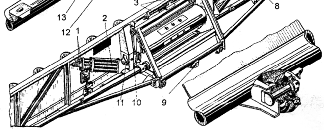
The height of the fingers above the soil is adjusted depending on the field relief and windrow density by repositioning the spacer bushings on the self-aligning support wheels 7 and 9. For wind protection and precise feeding of mass under the auger, a crop press 16 is used, featuring eccentric gudgeons 4 and levers 8 on adjustable stops 6. The pressure on the support wheels is regulated using a relief device consisting of extension springs 13 in housings 12 and rods.
Tensioning of the springs 13 with adjustment nuts 1 is performed once — immediately after mounting the new pick-up on the combine. Subsequently, this assembly does not require constant readjustment.
Reel and cutter bar adjustment
Precise reel adjustment eliminates harvest losses and prevents damage to the header's working components. In the extreme lower position, the reel tines must be at exactly the same distance from the cutter bar on both sides. To level the height, loosen the lock nuts on the hydraulic cylinder rods 35 and rotate the rods 31 themselves. The horizontal position of the reel is adjusted by hydraulic cylinders 34 so that with the rods retracted, the clearance to the auger flighting is at least 15 mm.
Check the synchronization of the reel hydraulic system every shift. During lifting, lowering, and horizontal movement, the reel must move smoothly without tilting or binding.
If it is necessary to move the reel further forward, the hydraulic cylinders 34 are disconnected from the sliders. Movement in this case is performed manually, securing the sliders in the holes of the supports 4 and 24. The side clearance between the reel tines and the header walls is adjusted by repositioning the washers on the gudgeons 17 of the reel shaft. To synchronize the operation of the hydraulic cylinders, perform a daily check.
- Raise and lower the reel using the hydraulics several times until it stops.
- Move the reel forward and backward several times to bleed the system.
The quality of the stalk cut directly depends on the clearances between the working elements of the cutter bar. Exceeding the specified values leads to mass crushing and increased losses behind the header. Clearances are adjusted using hold-down clips and plates, checking their parameters against technical requirements.
| Cutter bar assembly to be checked | Standard clearance, mm | Inspection conditions |
|---|---|---|
| Front part (segments 2 to inserts 23) | 0.1 | feeler gauge passes with resistance |
| Rear part (clearance) | 0.3–1.5 | — |
| Between hold-downs 5 and segments | no more than 0.7 | — |
Fine-tuning of the cutter bar and header auger
For a clean stalk cut and smooth operation of the cutter bar, it is necessary to precisely set the clearances between the friction plates and the finger bar. Adjustment is performed using shims. If the front side of the friction plates is worn, flip them to extend their service life. Adjust the hold-down clearance in place by carefully bending them with light hammer taps.
When replacing fingers or repairing the finger bar, ensure that the working surfaces of the inserts are in the same plane. If necessary, straighten the fingers with a hammer or by using a pipe section placed over the end of the finger. In a correctly adjusted mechanism, the knife should move easily by hand pressure.
- Offset of the knife head hinge axis — 2.5–3 mm
- Overtravel of knife segments at extreme points — 5–6 mm
- Deflection of the wobble drive belt at 40 N — 12–14 mm
The height of the knife is adjusted after loosening the mounting bolts by moving the lever head along its axis. In the extreme positions, the hinge axis of the clips should be 2.5–3 mm above the line of the knife back, and in the middle position — the same amount below. The overtravel of the knife segments beyond the center lines of the fingers in the extreme positions is set by lateral movement of the lever head. The tension of the drive belt for the wobble drive mechanism is adjusted with the tensioner pulley screw.
The clearance between the header floor and the auger flights directly affects the uniformity of crop flow. Increase it when harvesting high-yield long-straw crops and decrease it for short-stemmed and sparse crops. Adjustment is performed by moving the auger up or down using the adjusting bolts.
The zone where the fingers exit the auger housing is adjusted by rotating the crankshaft using the handle. When operating in dense crops, the fingers should extend and retract earlier so as not to interfere with the intermediate beater in picking up the mass. In sparse crops, the fingers are set for a late exit so that they push the mass further and prevent flow disruption. The clearance between the auger flight and the reflectors on the windshield should be minimal, while taking into account the radial runout of the auger.
Adjustment of the feeder house and pickup platform
For stable feeding of the mass into the threshing unit, it is necessary to properly tension the feeder house chains. Tension is adjusted by moving the lower shaft using tensioning screws with springs. In this case, the clearance between the feeder house slats and the floor of the feeder house should be between 5 and 10 mm. This clearance is set by installing or removing washers between the bracket and the block nut.
- Loosen the lock nut of the feeder house tensioning screw.
- Compress the spring with the adjusting nut to a length of 90 ± 5 mm.
- Tighten the lock nut until it hits the bracket to fix the position.
Chain tensioning is performed by moving the guide roller or the drive shaft with the slide bolts loosened. The parallelism of the shaft and the roller is strictly controlled according to the marks on the frame sides. The sag of the lower chain strand relative to the roller on the side should not exceed 5 mm. The pressure of the crop guide on the mass in the upper part of the conveyor is adjusted by repositioning the stop limits.
- Clearance between slats and the chamber floor — 5–10 mm
- Pressure of gauge wheels on the soil — 250–300 N
- Clearance from pickup fingers to the soil — 20–30 mm
- Clearance from stem stripper to the belt — 70–90 mm
When working with a pickup platform, it is important to adjust the pressure of the gauge wheels on the soil using the springs of the unloading device. The pressure force should not exceed 250–300 N. The clearance between the ends of the pickup fingers and the field level is adjusted by repositioning the spacer bushings on the gauge wheel fork posts. When picking up fallen windrows, the fingers can be lowered to the ground directly from the combine cab.
To avoid overloads, the deformation of the pickup unloading springs is limited by special sleeves. During travel and transportation of the combine, these sleeves must be locked with retainers.
The stem stripper is mounted with a clearance of 70–90 mm between its working edge and the conveyor belt. Below is a table of the main malfunctions of the header and pickup platform, which can be eliminated by adjusting the components in the field.
| Malfunction and its manifestation | Method of elimination and adjustment |
|---|---|
| The cutting apparatus cuts stems poorly, the knife jams | Adjust clearances with shims under the friction plates, bend the hold-downs with a hammer. Check the flatness of the finger liners; straighten them with a pipe if necessary. Check the position of the hinge axis (2.5–3 mm deviation) and the overtravel of the knife segments (5–6 mm). |
| Stems jamming between the auger and the header floor | Adjust the clearance by moving the auger up or down using bolts, depending on the height and density of the crop. |
| Stems jamming between the auger fingers and the floor when picking up windrows | Change the position of the finger exit zone from the auger housing by turning the crankshaft with the handle. |
| Jumping off or breakage of the feeder house conveyor chains | Adjust chain tension (spring length 90 ± 5 mm). Align the parallelism of the drive shaft and guide roller according to the marks on the frame. Check chain sag (not more than 5 mm). |
| Crop mass is thrown back onto the auger from the conveyor | Adjust the mass compression force with the crop guide using the stops; check the tension of the feeder house chains. |
| Breakage of an auger finger | Replace the finger. Adjust the finger exit zone with the crankshaft according to the volume of the passing mass. |
| Grain losses by the pickup (skipping the windrow) | Reduce the clearance between the fingers and the soil to 20–30 mm by repositioning the bushings on the wheel posts. Replace broken spring fingers. Set the stem stripper clearance to the belt within 70–90 mm. |
| Windrow piling up in front of the pickup | Increase the linear speed of the conveyor belt (bring it into compliance with the combine's travel speed). |
| Reel skews during lifting and movement | Check the condition of the guide supports and adjust the position of the reel support mechanisms. |
Read next
Farm machinery For agronomists
Influence of design and power parameters on the operation of a combine harvester threshing unit
Farm machinery For agronomists
Design features and advantages of double-drum threshing units of Yenisei combine harvesters
Farm machinery For agronomists