
Design and operating principles of the UF-1501 mounted sprayer
4 min read
- Nominal tank capacity — 1500 l
- Actual tank capacity — 1750 l
- Boom working width — 15–28 m
- Spray height — 500–2200 mm
- Operating system pressure — 0.8–10.0 bar
- Diaphragm pump output — 240 l/min
Design and operating process of the UF-1501
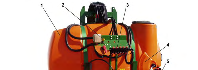
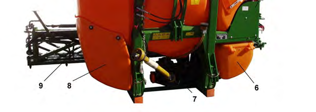
The UF-1501 mounted sprayer is designed for chemical plant protection of field crops against pests and diseases, as well as for applying foliar top dressing with liquid fertilizers. The machine's design is based on a sturdy frame, which holds the main tank for solution 1, a diaphragm pump 7, a manual control unit 3, and a folding five-section distribution boom 9. The liquid level in the tank is monitored via a float sensor and a level gauge scale 4. A special shower nozzle 3 is provided for cleaning the inner walls of the tank after operation, and a hydraulic agitator 4 is used to maintain the uniformity of the mixture.
The supply of the working solution is provided by a six-cylinder diaphragm pump, model VP-280, driven by the tractor's power take-off shaft at 540 min-1. The pump delivers the solution at a rate of 240 l/min at a pressure of up to 20 bar. The control unit contains a regulating valve 1, a switching valve 2 (position A — ON, position B — OFF), a pressure gauge 3, and five section valves 4. The overall system pressure is adjusted by the regulating valve, while the pressure in each individual boom section is set by knob 5. Each of the five sections can be switched off or on using special levers 6 (position C — ON, position D — OFF).
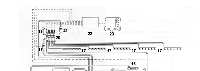
For the safe preparation of the mixture from powders and poorly soluble preparations, an auxiliary mixing tank 11 is mounted on the sprayer. The technological process operates in a closed cycle. The solution is drawn from the main tank 1 by the pump 10 through the step-less switch A and the suction filter 9.
Then, the liquid is pumped under pressure through switch B and a self-cleaning filter 15 to the pneumatic unit with a regulating valve 8. After passing through the flow meter 21, the flow is directed to the section valves 20 of the control unit, from where it is distributed via hoses to the boom nozzles. The nozzles are spaced 50 cm apart and spray the preparation onto the treated crop. A portion of the solution from filter 15 is continuously diverted via valve C to the hydraulic agitators 4, the intensity of which is adjusted by changing the valve position.
Adjustment and setup for the specified operating mode
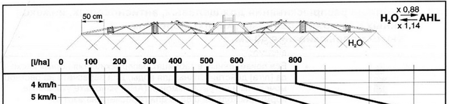
For accurate application of preparations, it is necessary to correctly calculate the liquid flow rate and configure the distribution system. The first step is to determine the required output of a single nozzle using the formula: q1 = QBV / 600n, where Q — target application rate of working solution (l/ha), B — working width (m), V — operating speed (km/h), n — number of nozzles on the boom. Based on the calculations and the calibration table, the nozzle type is selected, taking into account the planned travel speed, application rate, and spray pattern. Before starting operations, the entire system must be calibrated using clean water to verify the actual output.
Discrepancies between the actual flow rate and the calculated parameters lead to reduced treatment efficiency or plant scorching due to local overdosing of the preparation. Always perform a flow test with clean water before each trip to the field.
The sprayer calibration is carried out in several sequential steps to minimize errors when working with pesticides.
- Fill the sprayer tank with clean water and start the hydraulic agitator to stabilize the pressure.
- Use the regulating valve to set the calculated operating pressure on the pressure gauge.
- Engage the sprayer while stationary and ensure all nozzles are functioning without interruptions and producing an even spray pattern.
- Place measuring containers under the nozzles on the left, middle, and right sections of the boom and collect the discharged water for several minutes.
- Divide the volume of collected water by the exact measurement time (in minutes) for each nozzle and calculate the average actual flow rate (qf, l/min).
- Compare the obtained qf value with the calculated q1 indicator. If they differ, adjust the pressure using the pressure-reducing valve and repeat the measurement.
Monitoring application rate in field conditions: fill the tank with a precisely measured volume of solution and perform the treatment until the tank is completely empty, then stop the unit immediately. Measure the area actually treated. By dividing the volume of the applied solution by this area, you will obtain the real application rate in l/ha. If it needs to be increased, raise the operating pressure in the system; if decreased, lower it.
Read next
Farm machinery For agronomists
Classification and design features of modern agricultural seeders
Greenhouses and covers For gardeners
Artificial mist system installation for the propagation of plants using green cuttings
Farm machinery For agronomists