
Design and operating principle of the DKSh 64 Volzhanka irrigation machine
7 min read
The DKSh-64 "Volzhanka" sprinkler machine is designed for irrigation of low-growing field and vegetable crops, as well as permanent cultivated pastures and meadows. The machine has two wings, 4 and 11, which are mounted on both sides of the irrigation pipeline 1 during irrigation.
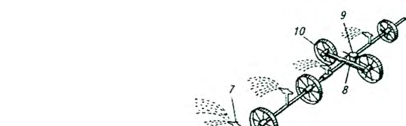
a – general view; b – drain valve; 2, 12 – hydrants; 3 – feeders; 4, 11 – wings; 5, 10 – wheels; 7 – sprinkler head; 8 – drive carriage; 9 – engine; 14 – drain holes; 15 – bolt; 16 – valve
Irrigation with each wing is carried out positionally by drawing water from hydrants 2 and 12, located 18 m apart. Each wing consists of a water-conducting pipeline 6, support wheels 5, a drive carriage 8, and sprinkler heads. The pipeline is assembled from aluminum pipes 12.6 m long, which simultaneously serve as the axle for the support wheels 5. Medium-range sprinkler heads 7 are equipped with self-alignment and barrel rotation mechanisms. The self-alignment mechanism is a tubular articulated link with a sealing washer and a counterweight. During irrigation, the counterweights keep the devices in a vertical position. The barrel rotation mechanism is equipped with an oscillating rocker arm with a paddle. The water jet exiting the nozzle of the device hits the rocker arm paddle and deflects it. Returning to its original position, the rocker arm rotates the device barrel by an angle of 3–5°. The nozzle orifice diameter is 7 mm. A drain valve 16 is mounted on the flange of each pipe, consisting of a metal plate and an oval-shaped rubber cuff. After the hydrant valve is closed, the cuffs move away from the holes 14 and release water from the pipe. During irrigation, the cuffs cover the holes 14. Each wing is rolled from one position to another using a 3 kW gasoline engine 9 mounted on the wing carriage. The engine 9 drives the running wheels 10 of the carriage and the irrigation pipeline 6. The reverse handle allows the machine to be stopped and set to move forward or backward. The handle is engaged before starting the engine or at a low rotational speed when the engine clutch is disengaged. The pipeline 6 is assembled at the edge of the field opposite a hydrant and connected to it with a flexible hose. After the application rate is delivered, the hydrant valve is closed, the hose is disconnected, the engine is turned on, the first wing is rolled to a new position, and the devices are set to a vertical position. After turning off the engine, the pipeline is connected to the next hydrant, and irrigation begins. The second wing is connected to the first hydrant and put into operation. Both wings irrigate simultaneously. The sprinkler is supplied in six versions with wing lengths of 400, 350, 300, 250, 200, and 150 m. One operator services two to three machines. Rainfall intensity is 0.24 mm/min.
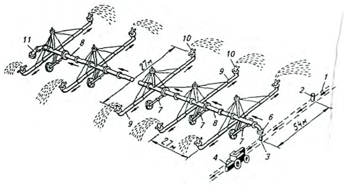
The DF-120 "Dnepr" sprinkler machine is designed for irrigation of all crops, meadows, and pastures with a plant height of no more than 2 m. Irrigation is carried out positionally from hydrants 2, 3, and 5 of a closed irrigation network located 54 m apart. The machine is equipped with self-propelled support carriages 7, upon which the water-conducting pipeline 8 rests with outriggers 9, medium-range sprinkler heads 10, and intake devices 6. The outriggers and links have stabilizing cable braces and guy wires.
1, 11 – pipelines; 2, 3, 5 – hydrants; 4 – power plant; 6 – intake devices; 7 – support carriage; 9 – outriggers; 10 – sprinkler heads
Operating features and machine automation
For wheel drive, electric motors with starting equipment are mounted on the carriages. The electric motors receive power from the power plant 4 (tractor with a mounted generator). The pipeline is connected to one of the irrigation network hydrants, and irrigation is performed.
Upon completion of irrigation, the following operations are performed:
- hydrant 3 is closed;
- intake device 6 is moved to the transport position;
- the pipeline is drained of water;
- the supply cable connectors of the carriages are connected to the power plant.
The machine and tractor move synchronously to the next hydrant. The straightness of the pipeline is ensured by a carriage movement synchronization mechanism. If any carriage moves ahead, a magnetic starter switches off the geared motor, and the carriage stops. In the event of an unacceptable bending of the pipeline, a signal lamp on the control panel goes out and an audible alarm sounds. The distance of the machine from the hydrant line is adjusted by changing the speed of the first and last carriages using buttons on the control panel in the tractor cab. To transport the machine from one field to another, the carriage wheels are turned by an angle of 90°.
| Indicator | Maintenance standard |
| Tractor operator (at a rate of 600 m3) | 1–4 machines |
| Electrician | 4–8 machines |
The machine productivity at an application rate of 300 m3/ha is 1.4 ha/h. Rainfall intensity is 0.3 mm/min.
Design of the "Fregat" sprinkler machine
The "Fregat" DMU self-propelled sprinkler machine consists of a multi-support pipeline 3 moving in a circle, made of steel pipes of a special specification, mounted on two-wheeled carriages 4. The pipeline is connected to the riser 2 of hydrant 1 located in the center of the irrigated area. Above the hydrant, there is a stationary support with a swivel elbow, around which the machine rotates.
a – general view; b – hydraulic drive diagram; 1 – hydrant; 2 – riser; 3 – pipeline; 4 – carriage; 5 – cable; 6 – sprinklers; 7 – drain valves; 9, 21 – springs; 10, 19 – rods; 11 – mercury switch; 12 – stem; 20, 25 – levers; 14, 26 – throttle and distribution valves; 15, 16 – hoses; 17 – filter; 18 – pin; 22, 27 – pushers; 23 – stopper; 24 – drain cock; 28 – piston rod; 29 – hydraulic cylinder; 30 – drain pipe
Medium-range circular sprinklers 6 and an end long-range sprinkler for irrigating the corners of a square field, covering a sector with a radius of 25 m, are installed on the pipeline. Each carriage is equipped with a hydraulic drive that operates under irrigation water pressure as follows. Water from pipeline 3 flows through filter 17 and hose 16 into throttle valve 14, and then through hose 15, distribution valve 26, and hollow piston rod 28 into hydraulic cylinder 29. Since the piston rod of the hydraulic cylinder is fixed to the frame and the cylinder is free, it rises under water pressure. A lever 20 is attached to the cylinder; its opposite end is connected to the front 27 and rear 22 wheel pushers, which engage with the lugs and rotate the wheels. The switching rod 19, sliding inside the upper part of lever 20, is connected by a fork of the distribution valve to lever 25. Lever 20 pushes the rod pin; it rises and rotates lever 25, which acts on valve 26 via the stem and lowers it. The latter shuts off the water supply to the hydraulic cylinder and opens the drain port. Under the action of return spring 21 and its own weight, the hydraulic cylinder descends and pushes the water out into drain pipe 30. The wheel pushers move backward and engage with the next lugs. Upon reaching the fork on the rod, lever 20 pushes it, rotating lever 25, which, having gripped the collar of the stem, opens the valve and closes the drain port. Water enters the hydraulic cylinder, and the cycle repeats. Carriages located at different distances from the center of rotation move at different speeds, so each of them has a speed adjustment mechanism. If one of the carriages lags, the pipeline bends and pulls the attached rods 10, which move stem 12; its bevel presses on the roller of pressure lever 13, which, in turn, presses on the stem of the throttle valve, forcing valve 14 to lower. The passage opening of the valve increases, the hydraulic cylinder fills with water faster, and the speed of the carriage increases. This continues until the carriage is back in line with the others. When the bend in the pipelines is leveled, the water supply returns to normal. The movement speed of the carriage is regulated by changing the working length of stem 12. The rotation frequency of the machine (0.47–0.11 rev/day) and, consequently, the irrigation rate (240–1250 m3/ha) are regulated manually on the last carriage using a speed-setting cock, which changes the water supply to its hydraulic drive. The cock is equipped with an arrow and a scale. After the irrigation rate is applied, the machine is moved to the next hydrant.

Read next
Farm machinery For agronomists
Current state and development prospects of domestic grain harvesters
Farm machinery For agronomists
Design and operating principles of the UF-1501 mounted sprayer
Farm machinery For agronomists