
Selection and installation of factory-made and DIY film greenhouses
17 min read
Factory-made greenhouses: assembly of "Urozhay" and "Metro" models
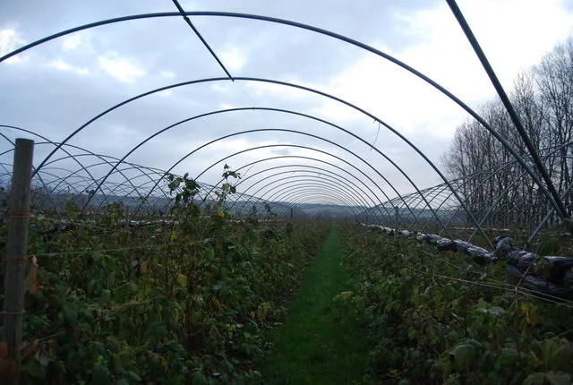
The factory-made film greenhouse "Urozhay" is in high demand due to its sturdy aluminum tube frame and ease of assembly. Structural elements are connected to each other using brackets. The assembly does not require highly specialized skills and is carried out in several stages.
- Assemble the end walls of the structure.
- Connect the intermediate frames to each other.
- Install the assembled frame on 12 supports in its permanent location.
- Secure the film covering with shaped spring clips with rubber gaskets.
This fastening system ensures reliable tightness, protecting the film from gusts of wind and accidental damage. The lower free edges of the sheet must be covered with soil. To provide rigidity to the structure and prevent skewing and sagging of the material, wire tensioners are used, which are attached directly to the frame components. To ventilate the greenhouse, the curtain doors located at the ends are opened.
When installing the greenhouse, secure the frame firmly using anchors; otherwise, strong gusts of wind will overturn the structure. For the winter, the system must be dismantled: components are cleaned of dirt, dried, and stored in an enclosed space.
Similar design solutions are applied in the "Metro" arch greenhouse. Its frame consists of 5 arches connected by longitudinal ties. After assembly, the structure is rigidly fixed with pins driven into the soil through holes in the brackets. The film is pressed against the frame with wire stretched over the arches, and its lower edges are covered with soil. The greenhouse is ventilated through end doors or by rolling up the side enclosure.
Amateur greenhouses: assembly features of stationary and winter structures
Amateur greenhouses vary in shape, but most often they are covered with polymer films, and less frequently with glass. In practice, three main types are popular: lean-to wall-mounted, arched, and gable with frame covering. The most common option remains a standard stationary greenhouse placed on a level plot. To build it, holes are dug at the corners of the future structure, and wooden post-supports are installed.
Before being buried, the lower ends of the supports are treated with resin to prevent rot. Cross and longitudinal rails are rigidly attached to the upper ends, after which the soil around the supports is thoroughly compacted. Then, slopes, side, and intermediate supports are mounted. Doors made of wooden frames covered with polyethylene film are hung at the ends.
- Standard greenhouse size — 4x6 m
- Film sheet size — 6.1x8.4 m
- Edge fixation on the rail — 2-3 turns
To seal the side walls and roof, solid film sheets are welded. To ensure the connection is reliable, the edge of the film is wrapped around a wooden rail and nailed down. The lower part of the sheet is covered with soil for wind protection. Ventilation is carried out through open doors or with the help of special bobbins onto which the side enclosure is wound.
It is recommended to keep a barrel of water inside the greenhouse. During the day, it accumulates solar heat, and at night, it gradually releases it, smoothing out temperature fluctuations and protecting plants from light frosts.
| Parameter | Value |
|---|---|
| Film consumption | 0.3 kg per 1 m2 |
| Film thickness | 0.15 m |
A winter gable greenhouse with a roof made of hotbed frames is suitable for year-round cultivation. It is characterized by high thermal insulation and excellent light transmission during the cold season. Its frame is assembled from wooden beams, aluminum, or polygonal profiles. Most often, farms use the more accessible wooden version.
Construction of a wooden frame requires precise marking of angles and cuts. Before assembly, the length of all identical beams must be checked. Bevelled end cuts on rafters and braces are made in advance according to templates cut out from the blueprint. Angle a is required for the upper cuts of the rafters, angle p — for the lower ones, angle y — for the top of the braces, and angle 5 — for their lower part.
The length of the braces is finally adjusted on-site only after the extreme rafter trusses are set strictly vertically. It is recommended to pre-draw all cut lines both on the assembly site and on paper templates. With correct marking, these lines should match perfectly. Only after such verification are the beams cut according to the marked contours.
Next, stakes are prepared for marking on the area where the greenhouse supports are to be installed. It is necessary that the stakes have the same cross-sectional profile as the beams for the supports. The beams for 30 cm are longer than what is required for the supports. These excess 30 cm are cut off from the beams, and stakes are made from them with exactly the same cutting profile; this is necessary so that when driving the stakes into the ground, they do not shift to the sides and do not change the brackets. On all shoulders to the frame beams.
To ensure that screws driven into the beams do not hit each other or the nails already driven into the timber, and to prevent the ends of the beams from splitting, adjacent holes should be offset slightly in opposite directions from the center of the shoulder. Nails must pass through the centers of the end cuts.
Check the screw slots; if they are too shallow, deepen them with a hacksaw so they can be tightened firmly.
The prepared brackets 1-4 should be screwed on in advance. When determining the position for the brackets, ensure they are set 1 mm back from the end cuts of the beams—this ensures a tighter fit of the beams when assembling the frame.
Place the brackets on the beams in the required positions and trace the screw holes onto the timber with a pencil. Mark the centers of these outlines on the beams with an awl and drill them using a drill bit smaller in diameter than the screw. Drive the screws into these holes to hold the brackets to the beams. Paint the prepared beams with oil paint.
Prepare a site for the greenhouse 1 m wider and longer than the greenhouse itself. Dig over the soil on the site, level it, and compact it. The surface of the site must be horizontal. On the site prepared in this way, lay out the perimeter of the greenhouse footprint using the longitudinal and transverse foundation beams. Proceed with further work in the sequence shown in Fig. 32.
The sequence of the ten operations shown in the figure must not be changed arbitrarily.
Assemble the roof trusses on the ground. Once assembled, place them onto the tops of the vertical posts and secure them with 150-200 mm nails. For structural strength, reinforce the joint between the posts and trusses with strips of thin galvanized iron, nailed or screwed from the outside.
The panels covering the base of the greenhouse are easiest to cut from slate using an ordinary carpenter's hand saw with medium-sized teeth. The height of the strips should be about 45 cm so that the panel, when fixed to the lower foundation beam, extends 15 cm into the soil.
Plates made of asbestos-cement boards, which are thicker than slate, can be cut using an electric drill with a carbide-tipped bit (drill holes right next to each other along the entire cutting line).
The asbestos-cement or slate cladding of the greenhouse bed can be replaced with boards painted thoroughly with oil paint. Place the boards vertically, flush against each other, and nail their tops to the lower foundation beams. The bottom of the boards is held in place by the soil, and to reduce the impact of dampness, cover the bottom of the boards on both sides with roofing felt.
Nail or screw locking devices onto the frame in the necessary places, and drive screws into the roof frames and rafters to secure the frames to the roof.
In regions characterized by unfavorable atmospheric conditions (heavy and frequent precipitation, large temperature fluctuations in summer), it is useful, in addition to covering the frames with a second layer of film on the back, to make roofing felt drip edges on the greenhouse. These will divert water away from the ridge boards and from the upper and lower foundation beams of the posts, which will prolong the service life of the greenhouse and also reduce warm air leakage through gaps between the roof frames and cold water seepage through them into the greenhouse.
The additional covering and drip edges are made as follows:
- Cover the back side of the frames with film just like the front side.
- Cover the ridge of the roof along its entire length with a strip of roofing felt, extending 3 cm below the boards forming the ridge on both sides.
- To divert water from the upper foundation beams, nail strips of roofing felt about 7 cm wide to the downward-facing edges of the bottom rails of the frames. By protruding 5 cm below the frames, they not only reliably protect the upper foundation beams from atmospheric precipitation but also enhance the sealing of the greenhouse.
- To divert water from the lower foundation beams, nail strips of roofing felt directly to the foundation beams themselves.
- To protect the rafters from water, nail strips of roofing felt 4 cm wide to the side rails of the frames lying on the roof.
- On the left and middle frames of each section, nail the strips only to the left side rails; on the right frame of each section, nail the strips to both side rails.
- When placing frames on the roof, lay the left frame first, then the middle, and finally the right one.
A very important warning must be given here. Roofing felt on the roof melts slightly in hot weather and can stick quite firmly to it over the summer. This can be avoided by covering the inner side of the roofing felt with thin paper and smoothing it with a slightly heated iron.
For convenience, a pathway should be equipped inside the greenhouse. It should be made the same width as the door openings.
The walls of the pathway are faced, just like the outside of the greenhouse, with slate sheets that go 15 cm into the ground and rise above the ground to the level of the lower frame beams of the supports. In the pathway, close to the sheets where they overlap, pieces of pipe are driven into the ground, protruding 5-7 cm above the sheets 1; these are tied with wire 3, the end of which is secured to a nail 4 specifically driven for this purpose into the lower longitudinal beam of the support frame. Above the pathway facing sheets, small railings 5 are installed. To do this, wooden plugs 6 are driven into the ends of the pipes 2, with their end faces aligned at the same level. Battens for the railings with rounded upper edges are nailed to the plugs.
Next, so-called "aprons" 7 are installed. They are rectangular pieces of film measuring approximately 1.5x2 m. Their long side is attached to the lower frame beams of the supports with thumb tacks, stretched over the bed, passed over the railings, and the free side is lowered into the greenhouse pathway. To prevent the film from sagging, battens 8 are nailed to the hanging edges of the aprons.
During the day, when it is warm, the aprons are wound onto their battens and laid along the greenhouse walls, and as soon as the plants grow and begin to touch the film, the aprons are removed entirely and stored until the following year. In other words, the aprons create a kind of hotbed inside the greenhouse.
For the frames removed to ventilate the greenhouse (or hotbed), a rack is equipped, consisting of two pairs of stakes driven into the ground and connected in pairs by battens at the bottom and top.
It should be noted that greenhouses covered with plastic polymer materials, as a rule, have a cross-sectional profile of the roof in the form of a broken line (polygonal profile). An example of such a design is a greenhouse with flexible frame joints.
The greenhouse frame with flexible frame joints is assembled from strands positioned perpendicular to the longitudinal axis of the cover with a spacing of 100 mm. Each strand is made of identical wooden bars 370 mm long, with semicircular cutouts made in their ends.
When joining the bars 2, longitudinal ribs 3, made of wood or cut from metal pipes, are inserted into the resulting circular holes. At the top and bottom, the bars are connected by flexible strips 1, which are cut from old conveyor belts or inner tubes.
Then, the middle of the frame is raised, connected at the support points with braces 5—wooden rods—to provide rigidity, and covered with polyethylene film. The structure is reliable and convenient to operate. It is easy to disassemble for the winter and store in a folded state. Greenhouse dimensions can vary.
The greenhouse structure can be pyramidal. Its advantage is that it warms up faster than a standard one. This is an important factor during short daylight hours. The resulting condensation and water run off along the inclined surfaces.
A lean-to greenhouse is very convenient. The optimal option is a single-pitch greenhouse against the south side of a house or shed. Its advantages are that the wall of the outbuilding is used as a load-bearing element of the frame, protecting against cold northern winds. The greenhouse can be equipped with electric or water heating, as well as an entrance from inside the building.
A single-pitch greenhouse can be operated throughout the year. It uses frames measuring 1060x1600 mm. The roof slope depends on the climatic conditions of the area. The slope angle should be 20-30 degrees.
The wall of the house (or other outbuilding) adjacent to the greenhouse should be covered with a waterproof layer of roofing felt, film, or two to three layers of water-resistant enamel or paint to protect it from dampness. It is even better if heating pipes run through the wall or a radiator is installed (as in the modification of the lean-to greenhouse in Fig. 38).
The greenhouse frame is made of wooden beams or metal angles. One side rests on the wall, and the other on a small base foundation made of brick, stone, or wood.
A portable small-scale greenhouse is very advantageous, allowing for three to four rotations of vegetable crops, extending the period of fresh vegetable consumption. A portable greenhouse allows for accelerated ripening of many crops and significantly increases yield.
| Greenhouse area | Dimensions | Film consumption |
| 16 m2 | 6x3 m, 2x2.2 m | 96 m2 |
Such a greenhouse is easy to build yourself from a metal structure and polyethylene film.
The portable greenhouse has the advantage that tillage, sowing, and plant care can be carried out before installing it over the bed, which is much more convenient than working inside a greenhouse. In addition, such a greenhouse can be made lower.
When there is still snow on the ground, a greenhouse can be used for growing greens. Later, it is moved to grow transplants, first cabbage, and then tomatoes and cucumbers. Transplants in a plastic greenhouse receive sufficient light and acclimatize better than indoors. In this way, you can obtain vegetables until late autumn or until heavy frosts.
Figure 39 shows a mobile greenhouse — a more convenient version of a portable one.
The base of such a greenhouse is mounted on runners made of water pipes with a diameter of 5.08 cm. Construction features of the assembly:
- Every 4 m, 2 m high posts are welded to the runners.
- At the top, tin trays are attached to the posts to collect water and provide structural strength.
- Roof arches are connected by trays, with each pair of adjacent section arches being pivotally fixed in the tray area.
- The end arches are fixed rigidly.
- At the ends, at a height of 80 cm, a pipe connecting the sections is welded; it also acts as a greenhouse tie.
- A rail is attached to the pipe, and a film sheet is attached to the rail.
- The sheet has a reel at the bottom, onto which the film is wound.
Doors in such greenhouses are made on the side wall. The structure is moved using a winch or a tractor.
Each of the listed types of greenhouses has its own advantages. Decide for yourself which one suits you best.
Since a greenhouse is generally a stationary structure (unlike a hotbed), we do not recommend using just any material that comes to hand during construction. In addition to purely architectural and aesthetic shortcomings, it is impossible to create optimal conditions for plant development in such greenhouses. Do not spare the time and resources to build a greenhouse structure that meets the most demanding requirements.
Individual spring greenhouses are usually built without technical heating systems. The temperature regime necessary for plants in them is maintained thanks to solar energy.
The efficiency of using solar energy can be significantly increased by accumulating heat in the soil on clear, sunny days. A diagram of a greenhouse of this design is shown in Fig. 40.
Accumulation of solar energy in the greenhouse is achieved through air circulation via asbestos-cement pipes with a diameter of 10-20 cm, laid in a layer of clay at a depth of 40-50 cm. Air movement is carried out thanks to an electric fan with a power of 25-30 W.
With constant circulation during the day, warm air, passing through the pipes, transfers heat to a 20 cm thick layer of clay and to the greenhouse soil, and at night the air in the greenhouse is warmed up due to the accumulated heat. Therefore, the night air temperature is 4-5°C higher than in a regular greenhouse without heating.
The use of solar energy in a greenhouse can be improved thanks to a solar installation, in which a higher temperature of the heat carrier used is achieved. The solar collector (heater) consists of an aluminum housing with an area of 2 m2, in which eight pipes, a translucent glass enclosure, a heat exchanger, and thermal insulation are placed. The heat pipes in the heater zone are equipped with flat fins, and in the heat transfer zone — with annular ones. The heat-absorbing surface of the collector is covered with matte black paint.
Several types of solar collector designs have been developed, but the operating principle is the same for all and consists of the following: solar radiation, passing through the translucent enclosure of the heater, is captured by heat pipes and heats water or evaporates Freon. Hot water or Freon vapors, rising upward, are cooled in the heat exchanger by the air passing through it. The cooled water or condensed Freon vapors return to the heating zone under the influence of gravity.
Air is usually used as a secondary heat carrier. The power of air solar installations in sunny weather can reach 500-800 W/m2 of collector area. A solar installation is relatively simple to manufacture; its most labor-intensive part is the solar collector.
A box with dimensions of 1500x750x100 mm is knocked together from planed boards. In the upper edges, a rebate should be cut for glass insertion. On the outside, strips of iron are nailed to the edge of the box to install a second glass pane. The bottom and walls inside the box are lined with a layer of foam plastic approximately 20 mm thick. The inner cavity of the box is painted with black oil paint, having previously mixed 1 liter of paint with 1/3 of a piece of laundry soap dissolved in a small amount of water (the result will be a matte oil paint). On the outside, the box is covered with any paint for outdoor use. The radiator of the solar collector is fastened inside the box. It is a coil made of copper or brass tubing with an internal diameter of at least 15 mm. 15-20 copper or brass angle strips are put on each pipe elbow. Both outlets are connected to water pipes.
The solar collector radiator is started by making U-shaped tube sections. They are bent using a device similar to a pipe bender. When manufacturing the U-shaped sections, segments of steel pipe with a slightly larger diameter are used as levers. They are placed over soft copper or brass tubes to prevent them from bending in other places.
Next, angle strips are made. Cut strips of copper or brass (not yet bent into an angle) are stacked and clamped in a vise. The preparation process includes the following steps:
- Drill a hole, into which a segment of the tube from which the collector will be made is inserted to fix the workpieces.
- The workpieces are aligned and clamped in the vise again.
- After drilling the second hole, the strips are bent into an angle.
Now you can begin assembling the section. An angle strip is placed on both ends of the U-shaped tube. Using a highly active flux (such as LETI-120), the strip is soldered to the tube in both holes. Thus, all strips are fixed one by one. After assembling all sections, of which there are 7-8 in a collector, they are connected by soldering them with connecting tubes.
Self-centering adapter bushings (used to connect faucets to water pipes) are soldered onto both outlet tubes, and the collector is connected to the water pipes using couplings.
The collector glass is installed using a special putty, the composition of which is presented in the table:
| Component | Mass parts |
| Sifted chalk | 50 |
| Dry iron minium | 30 |
| Natural drying oil | 18-20 |
The solar collector is placed on a stand in a wind-protected area next to the heat accumulator. The surface of the solar collector must be perpendicular to the sun's rays, and two segments of rubber hose of the required diameter are inserted into the gap.
The heat accumulator is an ordinary 20 L barrel placed in a wooden box. It is necessary to provide good thermal insulation for it:
- A cross-shaped wooden stand is placed at the bottom of the box, and all free space is filled with felt or cotton wool.
- The barrel is placed in the box on the stand, and all free space between the barrel and the walls of the box is also filled with cotton wool, with the thickness of the insulating layer being at least 80 mm everywhere.
- The removable lid of the barrel is insulated with a cotton mattress (its thickness is also 80 mm).
Read next
Greenhouses and covers For gardeners
Building a frame greenhouse with a gable roof with your own hands
Greenhouses and covers For gardeners
Fabrication and installation of collapsible portable film covers for vegetable crops
Greenhouses and covers For gardeners